


Form No. S3423-1112
Supersedes S3423-912
Page 3 of 28
LEDO
M
1S63CTG 1S84CTG 1S06CTG
)HP1/ZH06(gnitaRlacirtcelE 1-06-802/032
egnaRegatloVgnitarepO CAV791-352
yticapmAtiucriCmuminiM 0.620.430.83
eziSeriWdleiF+ 8#6#4#
eziSeriWdnuorG 01#8#6#
.xaMrekaerBtiucriCroesuFyaleD++ 040506
ROSSERPMOC
stloV 1-06-802/032
)802/032(spmAdaoLdetaR 0.31/2.116.91/4.616.32/2.91
tnerruCnoitceleStiucriChcnarB 7.612.126.52
)802/032(spmArotoRdekcoL 28/2869/69811/811
ROTOMREWOL
B
)rotoMMCE(rewopesroH deepSelbairaV4/3
stloV 1-06-802/032
)MFCdetaR@2#egatS(spmArotoM 4.33.44.4
)2-CFRODnodesaB(RETNECWOL
F
stloV 1-06-802/032
spmA 41.241.241.2
ROTOMPMUPRETAEHREPUSE
D
stloV 1-06-802/032
spmA 51.051.051.0
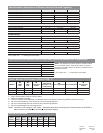
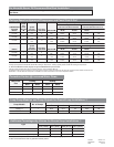
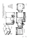
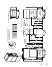
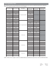
Specifications (Compressor & Blower Sections Stacked Together)
+75°C copper wire ++ HACR type circuit breaker
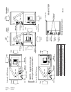
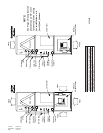
Specifications (for Blower Section Only when Remote Mounted from Compressor)
+75°C copper wire ++ HACR type circuit breaker
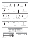
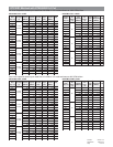
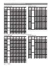
Indoor Blower Performance (Rated CFM)
1
Airflow Corrections
fo%
detaR
wolfriA
latoT
yticapaC
)HutBM(
elbisneS
yticapaC
)HutBM(
rewoP
tupnI
)WK(
fotaeH
noitcejeR
)HutBM(
latoT
yticapaC
)HutBM(
rewoP
tupnI
)WK(
fotaeH
n
oitprosbA
)HutBM(
%09589.0448.0879.0389.0889.0030.1879.0
DETAR000.1000.1000.1000.1000.1000.1000.1
%011010.1050.1520.1310.1010.1889.0510.1
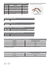
)detnuoMyletomeRfI(NOITCESREWOL
B
ledo
M
A-1BTG
epyT/P
H
deepSelbairaV4/3
)ALR(spmAroto
M
1.6
yticapmAtiucriCmumini
M
8
eziSeriWdleiF
+
41
rekaerBtiucriCro.xaMesuFyaleD+
+
51
NOTE: This applies only if blower section is remote mounted
from compressor section. When blower section is coupled
directly to compressor section, the blower is powered from the
compressor section.
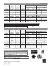
LEDOM
22
2
22
detaR
PSE
33
3
33
XAM
PSE
44
4
44
suounitnoC
wolfriA
55
5
55
etamilCdliM
traPninoitarepO
gnilooCdaoL
66
6
66
wolfriAdaoLtraPwolfriAdaoLlluF
77
7
77
taeHcirtcelE
wolfriA
1S63CTG51.006.000600705800210031
1S84CTG02.006.0057578051100510061
1S06CTG02.006.00090501003100810081
1 Motor will automatically step through the various airflows with thermostatic control
2 ESP = External Static Pressure (inches of water)
3 Maximum allowable duct static
4 Continuous airflow is the CFM being circulated with manual fan operation without any additional function occurring.
5 Will occur automatically for first 5 minutes of Part Load Cooling Operation.
6 Will occur automatically after five minutes of Part Load Cooling Operation.
7 Will occur automatically with control signal input.
NOTE: All values can be changed + 10% via the + adjustment dip switches on the tap select control inclusive in the GTB1-A
Blower Section (see Airflow Corrections for performance impact).