


performance. Special low capacitance cables enable even
greater distance between preamp and amplifier. It is desirable
to keep the left and right input cables close together throughout
their length to minimize the likelihood of hum pickup. Also, you
should avoid running them parallel to AC cords
-
these should
be crossed at right angles.
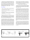
Output
The loudspeakers (or headphones) connect to the red and
black terminals on the back panel. These binding posts provide
several convenient alternative connecting methods. The screw
cap may clamp the bared wire end, or a “spade lug” attached to
it, but a better connection will be made by locating the hole drill-
ed through the shaft of the terminal when the cap is unscrewed.
Insert the twisted end of the bared wire so that the cap will
clamp it in place. Always be sure that no strands of wire are
unsecured, and that the bared end is not too long to risk contac-
ting other elements. A soldered end or fitting is the safest solu-
tion.
These terminals also accept standard plug-in “banana pin con-
nectors,” including the double ones with standard
3/4”
spacing,
available from electronic supply houses. These are the most
convenient, especially if you may wish to interchange speakers
occasionally.
It is important to maintain correct phasing of the speakers
when making their connections. Some speaker terminals are
coded red and black, or + and
-,
etc. It is important that the
“sense” of one speaker’s connections match the others. If one is
reversed, you will find that the sonic image has a “hole in the
middle,” and that it is deficient in bass. Speaker wire always
identifies one conductor to make this easy. There may be a
molded ridge in one lead, or the color of the insulation on one
wire is different, or the wire itself may be color coded. If pin
plugs are used, be suretheyare color coded, or that you follow
the indexing mark ononeside of the double connectors.
Select speaker wire of sufficient size to preserve the high
damping factor (and excellent speaker control) of your
amplifier. Standard 18 gauge lamp cord (“zipcord”) is satisfac-
tory for distances up to 30 feet for an
8
ohm speaker. As the
distance increases, larger wire sizes are recommended. The
next larger wire size is
#16,
and it is often preferred by perfec-
tionists. If you have 4 ohm speakers, the maximum cable length
for best results is halved.
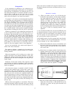
The black output terminals are electrically connected to the
chassis internally. Be certain that when the amplifier is operated
in its normal stereo mode that the red output terminals are never
connected together. In the special case when the amplifier has
been internally modified for monophonic bridged operation,
the output is taken from the two red terminals
only.
Then, the
black terminals are left unconnected.
Headphones are normally operated from the loudspeaker
outputs, but are usually connected through a junction box
which provides switching from phones to speakers. Such a box
usually provides some added resistance to reduce the sensitivity
of the phones, and thus minimize the likelihood of hearing com-
ponent noise, because of the low setting required at the volume
control. Some headphone boxes utilize a “common ground”
system which makes it particularly important that you carefully
observe the proper connections. While the black ground ter-
minals can be connected together, the red ones must not be.
Some headphones, such as electrostatic types, are less sen-
sitive and may need little or no resistance in series for normal
operation. These could be easily interchanged with the
speakers through the use of double banana plugs.
KIT ASSEMBLY INSTRUCTIONS
There are three basic rules for success in electronic kit
building:
1. Read the instructions carefully, and follow them in order.
2. Make secure solder connections which are bright and
smooth.
3. Check your work carefully after each step.
The DH-220 amplifier is a versatile component with
sophisticated circuitry which has been made remarkably easy
to build by individuals with many years of experience in the
design and engineering of the finest performing audio kits, and
in the preparation of their manuals.
Kit building should be fun, and we are certain you will find this
to be so. Assembly will be faster, easier, and more enjoyable if
you have someone help you by reading the steps aloud, selec-
ting the required parts, and preparing the necessary wire
lengths in advance as you proceed. Fatigue increases the risk of
error, so take a break rather than push to early completion.
There are relatively few separate components in this design, to
make it easy to pack everything away, if need be.
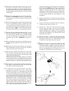
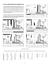
Your work area should have good lighting, the proper tools,
and a place where the large pictorial diagram can be positioned
within easy reach for checking. The tools should include:
1,
2.
3.
4.
5.
6.
7.
8.
9.
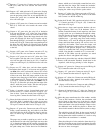
A 40 to 100 watt soldering iron with a
1/4"
or smaller tip which
reaches at least
600°F.
60/40 (60% tin) ROSIN CORE solder,
1/16"
diameter or
smaller. (Smaller diameters are easier to work with.)
A damp sponge or cloth to wipe the hot top of the iron.
A wire stripping tool for removing insulation. This can be a
single-edge razor blade, but inexpensive stripping tools are
safer, faster and easier.
A medium-blade screwdriver (about
1/4"
wide).
Needle-nose pliers (a long, narrow tip).
Diagonal or side-cutting small pliers.
Large “gas” or “slip-joint” pliers.
A
1/4"
“Spin-tite”
nut driver may be helpful, but is not
necessary.