


(7)
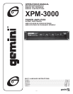
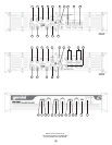
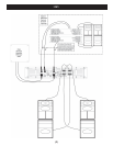
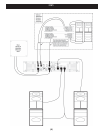
2. Connect the loudspeakers to the channel A and channel B SPEAKER
OUTPUTS (8, 9). THE TOTAL SPEAKER LOAD MUST BE AT
LEAST 4 OHMS PER CHANNEL FOR CHANNELS A AND B. If you
try to operate at a lower impedance, the amplifier will overheat and
then go into protection mode and stop operation until you correct the
load conditions.
3. If you choose to use additional amplifiers, connect the additional
amplifiers to the XPM-3000 using the LINE OUTPUT (1, 2)
connectors.
4. Set the CROSSOVER SWITCH (3) to FULL RANGE so that the full
range signal will go to the satellite channels (Channels A and B).
5. With the LEVEL CONTROLS (20, 21) of the channels set to zero
(fully counterclockwise), turn the POWER (23) on. Apply a signal to
the input of the amplifier. The level of the input signal should be as
high as you will ever need it to be. This way, it will be as high above
the amplifier’s noise floor as possible, ensuring an excellent
performance and signal to noise ratio. Adjust the LEVEL CONTROLS
for each channel to achieve the desired maximum listening level.
Note, when the clip LEDs light, there is distortion present in the
amplifier’s output section. If a clip LED remains on or flashes
repeatedly, reduce the signal level by lowering the input level control
for the channel that is clipping or reduce the level at the source.
Using the Signal Ground Lift Switch
Depending on your system configuration, sometimes applying the
ground will create a quieter signal path. Sometimes lifting the ground can
eliminate ground loops and hum to create a quieter signal path.
1. With the power amp on, listen to the system in idle mode (no signal
present) with the ground applied (the SIGNAL GROUND LIFT
SWITCH (15) in the left position).
2. Then turn the power off before moving the SIGNAL GROUND
LIFT SWITCH (15). Lift the ground by moving the SIGNAL GROUND
LIFT SWITCH to the right, turn the power back on and listen to
determine which position will provide a signal devoid of background
noise and hum. Keep the SIGNAL GROUND LIFT SWITCH in the
ground position if the noise level remains the same in either position.
CAUTION: DO NOT TERMINATE THE AC GROUND ON THE POWER
AMPLIFIER IN ANY WAY. TERMINATION OF THE AC GROUND CAN
BE HAZARDOUS.
Specifications
Output Power EIA: 1kHz @ 1% THD (100 Hz @ 1% THD for the
subwoofer channel)
Note: the power for channels A and B is given as per channel, both
channels driven
Frequency Response - 3 Channel Operation:
Channels A and B.......................................Crossover Frequency - 60 kHz
Subwoofer Channel.....................................20 Hz - Crossover Frequency
Frequency Response - Full Range Operation:
Channels A and B.................................................................20 Hz - 60 kHz
Crossover:
Type.................................................................2nd order Linkwitz-Riley
Crossover Frequency....................................................120 Hz/180 Hz
Low Frequency Boost:
Boost Frequency..............................................................................40 Hz
Boost Level..............................................................................+3 dB/+6 dB
Signal to Noise Ratio..........................100 dB below rated power, 8 Ohms
Damping Factor:
Channels A and B................................................................>300 @ 8 Ohms
Subwoofer Channel.............................................................>600 @ 8 Ohms
Slew Rate.................................................................................25 V/µS
Voltage Gain.........................................................................................33 dB
Input Sensitivity:
Channels A and B (for rated power at 8 Ohms)....................>300 @ 8 Ohms
Subwoofer Channel (for rated power at 4 Ohms)...................>600 @ 8 Ohms
Input Impedance Unbalanced....................................................10 kOhms
Input Impedance Balanced.......................................................20 kOhms
Power consumption.....................................................................1200 VA
Note: power consumption is given at rated power at 8 Ohms per channel
(Channels A and B), 4 Ohms on the subwoofer channel, all three
channels driven.
AC Power Requirement:
(power connection is factory configured)............................120V/ 60 Hz
230V/ 50 Hz
Indicators.......................................................................1 Power Indicator
1 Signal LED per channel
1 Clip LED per channel
1 Protect LED per channel
Cooling....................................2 Speed Dual Fan; Front-to-Rear Forced Air
Protection........................Short Circuit, DC, Thermal Cut-off, Sub/ultrasonic
Frequency Filters, In-rush Current Limiter, Turn-on Delay
Connectors:
Balanced/Unbalanced Inputs.......................................................1/4" Jack
Balanced Inputs..............................................................XLR Female Jack
Line Outputs...............................................................................1/4" Jack
Speaker Outputs (120V unit).......................................5-way binding posts
2 Parallel 5-way binding posts for subwoofers
Speaker Outputs (230V unit)...........Speakons (ch.A, ch.B and subwoofer)
Dimensions...................................19" x 13.75" x 3.5" (483 x 350 x 89 mm)
Weight....................................................................................31 lbs (14 kg)
* Specifications and design are subject to change without notice for
purpose of improvement.
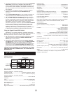
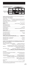
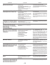
Ouput Power Chart:
Impedance
Subwoofers
A and B
Speakers
8 Ohms
8 Ohms
Not
Used
4 Ohms 2 Ohms
4 Ohms
Not Used
300
260
220
200
425
380
190
350
270
600
540
165
530
250
220