


(3)
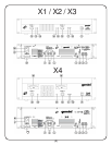
AC LINE VOLTAGE SWITCH: AC LINE VOLTAGE SWITCH (17) allows
reconfiguring amplifier for either 110-120V or 220-240V AC lines.
OUTPUT SECTION:
Disconnect unit from the AC power source before making any connections.
Pay close attention to polarity (shown on the back of the unit)
when connecting your speakers. Connecting your speaker systems
using the wrong polarity will not damage your speakers, but will impact
the quality of the sound (lack of bass and incorrect stereo image).
SPEAKER OUTPUTS: The SPEAKER OUTPUT (5,6,7) connectors are 3-
way binding posts that will accept a standard banana plug, spade lugs,
or bare wire. Make sure that all the connections are clean when using
bare wire connections. If any strands of wire from one connector touch
the adjacent connector, the sound will distort, and your amplifier will
overheat and go into protection mode.
NOTE: TOTAL SPEAKER IMPEDANCE MUST NOT BE LOWER THAN 4 OHM PER CHANNEL FOR
STEREO AND PARALLEL MONO MODES, AND 8 OHM FOR MONO BRIDGE MODE.
FRONT PANEL:
POWER SWITCH: The POWER SWITCH (9) turns the unit on and off.
POWER LED: The POWER LED (10) lights when the power is on. If the
POWER LED (10) does not light, refer to the troubleshooting guide.
SIGNAL LED: The SIGNAL LED (13) for each channel show when a
signal is present. In Mono Bridge mode, both the Channel 1 LED and
the Channel 2 LED will light in unison.
CLIP LED: The amplifier has true CLIP LED (14) to help you properly control
the amplifier’s output and achieve undistorted sound. The CLIP LED (14)
for each channel light when your signal level is so strong that the distortion
reaches 1% THD. The CLIP LED (14) should not remain constantly on or
flash repeatedly during operation. For clean sound reproduction, the CLIP
LED (14) should only light occasionally for an instant. If the LED remains
on or flashes repeatedly, you will hear distorted sound that can be damaging
to your speaker systems. If this occurs, reduce the signal level by
lowering the input level control for the channel that is clipping or reduce
the level at the source. If the CLIP LED (14) lights when no signal is
present, it may indicate an RF signal on the output which may cause
damage to speakers (the RF signal will not be audible). Please note
that when you are using the amplifier in the Mono Bridge mode, both
CLIP LED (14) of the bridged channels will operate simultaneously.
PROTECT LED: When you first turn on the amplifier, the PROTECT LEDS (11)
light briefly during a turn-on delay which indicates that the outputs are
disconnected internally. There will be an audible click when the outputs
reconnect and the PROTECT LED (11) will turn off. Otherwise, the
PROTECT LED (11) indicates that there is a problem either in the amplifier’s
external connections, load or temperature conditions or its internal
functions. If one of these situations occurs, the amplifier senses the
problem and automatically switches into protection mode. The LED will
light to warn you of the trouble and the amplifier will stop working. If this
occurs, switch off the amplifier and refer to the Troubleshooting Guide.
If the PROTECT LED (11) remains lit when resuming amplifier operation,
do not use the amplifier and contact an authorized service technician.
LEVEL CONTROLS: LEVEL CONTROLS (12,15) establish the input levels
required for each channel. Only the Channel 1 LEVEL CONTROL (15)
works in Mono Bridge mode.
OPERATION:
STEREO OPERATION:
THE AMPLIFIER’S POWER MUST BE TURNED OFF WHEN CHANGING
MODES OF OPERATION.
The unit has two channels for stereo operation. Each channel provides
a separate and discrete signal at the speaker outputs according to the
signal received at the inputs. The following instructions are for
applications with 4 Ohm or 8 Ohm speakers of matched power ratings.
1. With the power off, set the OPERATION MODE SWITCH (3) to the STEREO
position.
2. With the power off, connect your input cables to the Channel 1 and 2
inputs using the 1/4" INPUT JACKS (1, 2) of each channel.
INTRODUCTION:
Congratulations on purchasing a Gemini Power Amplifier. This state
of-the-art power arnplifier includes the latest features and is backed by
a three year limited warranty. Prior to use, we suggest that you
carefully read all the instructions.
FEATURES:
• State-of-the-art bi-polar output stage technology for the finest sound quality and reliability
• High output power to drive professional loudspeakers without clipping
• Comprehensive protection circuitry (Short Circuit, DC, Thermal Cut-off, Sub/Ultrasonic
Frequency Filters, Turn-on Delay, Main Fuse, Secondary DC Fuses)
• Three modes of operation - stereo, parallel mono and mono bridge
• Active 1/4" Jack balanced/unbalanced inputs
• Ground lift switch for flexibility in installations
• Signal LEDs and Clip LED for better control on X1, X2, X3 amplifers
• Large VU-meters and Clip LED for better control on X4 amplifier
• Efficient dual aluminum extrusion heatsink design with directly mounted output
transistors for no-fault operation
• Efficient air guide with front-to-rear airflow for thermal stability and reliability
• Compact 2U well balanced enclosure (3U for X4 model)
• Steel reinforced chassis construction for durability and longevity
CAUTIONS:
1. Read all operating instructions before using this equipment.
2. To reduce the risk of electrical shock, do not open the unit. There are
NO USER REPLACEABLE PARTS INSIDE. Please contact the Gemini
Service Department or your authorized dealer to speak to a qualified
Gemini Sound Products technician.
3. Be sure to allow adequate front and rear ventilation to avoid possible
heat damage to your equipment.
4. Be sure that AC power is OFF and all level controls are set to MINIMUM
before making connections. This will eliminate any chance of unexpected,
loud audio transients that could damage your speaker systems.
In the USA: If you experience problems with this unit,
please call 1 (732) 738-9003 for Gemini Customer Service.
Do not attempt to return this equipment to your dealer.
5. Be sure that AC power is OFF when changing modes of operation
and when changing the position of the Ground Lift Switch.
6. DO NOT EXPOSE THIS UNIT TO RAIN OR MOISTURE. Operators of
electronic equipment should in no way be in contact with water.
7. When connecting to AC power line be sure you haven’t lost the ground
connection by using an adapter or extension cord without a 3 prong plug.
8. DO NOT USE ANY SPRAY CLEANER OR LUBRICANT ON ANY
CONTROLS OR SWITCHES.
CONNECTION, CONTROLS AND
INDICATORS:
REAR PANEL INPUT SECTION:
1/4" INPUT JACKS: 1/4" INPUT JACKS (1, 2) accept a balanced as well as an
unbalanced line level signal. The unbalanced line uses a standard tip-sleeve
connection. The tip is positive and the sleeve is negative or ground. The
balanced line uses a tip-ring-sleeve connection. The tip is hot or positive
(+), the ring is cold or negative (-), and the sleeve is shield or ground.
OPERATION MODE SWITCH: OPERATION MODE SWITCH (3) switch is
used to set the unit for Stereo mode, Parallel Mono mode or Mono
Bridge mode.
AC POWER SECTION:
FUSE: Replace FUSE (8) with those of proper type and rating.
GROUND LIFT SWITCH : GROUND LIFT SWITCH (4) is used to lift the
balanced input connectors’ ground/shield from the amplifier’s ground.
When the signal ground lifted, the sound source disconnects from the
amplifier’s ground preventing ground loops which can generate hum and
noise. See the Ground Lift Switch Instructions for more detail.
AC INLET: AC INLET (16) is used to attach the power cord to the unit.