


5
Digital Audio Monitoring
On MS Series units equipped for digital audio, stereo digital signal(s) may be connected via the rear
panel BNC connector(s) labeled AES1, and, if present, AES2. Only one connector is needed per
stereo signal. The digital input(s) conform to the AES/EBU 75 ohm/BNC (AES-3id-1995) standard.
Another standard, S/PDIF 75 ohm coaxial, may also be monitored.
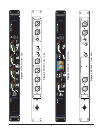
There are two Signal Present indicators for each BNC digital input. The indicator(s) on the rear panel
are adjacent to the BNC connector(s) and are labeled SIG. The indicator(s) on the front panel are
labeled AES1 (and AES2). Both front and rear indicators display identically. If the digital data is valid
and signal is present, they will glow GREEN. If the data is bad or no signal is present, they will glow
RED.
Both analog and digital signals may be connected simultaneously. The meters, speakers, phase
indicator, and headphone output will monitor the source selected with the A/D SELECT button,
which toggles between ANALOG and DIGITAL, with indicator LEDs showing the chosen source.
Analog Outputs
The XLR balanced Analog Outputs on a MS Series unit need not be used. However, they provide a
convenient, high quality balanced signal source, complete with their own SIG indicators to verify the
presence of signal. There is also a stereo GAIN TRIM control on the rear panel which may be varied
from -6 to +6 dB. Center rotation is 0 dB (unity gain).
The Analog Outputs are labeled Left and Right. With two-channel models, Channel 1 is assigned to
the Left out and Channel 2 is assigned to the Right output. With four-channel models, output
assignment switches (LEFT CHANNEL SELECTOR and RIGHT CHANNEL SELECTOR) are provided
for maximum flexibility. They allow any channel to be routed to either output. Indicator LED’s show
which channel is selected by each switch.
NOTE: In four-channel models, the HEADPHONE
out, the internal speakers, and the PHASE
indicator all monitor the two input channels that are assigned to the outputs.
When a stereo digital source is being monitored, the analog version of that signal will appear at the
Analog Outputs, allowing the MS Series unit to be used as a D/A converter.
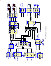
Normally, in the factory-preset condition, the VOLUME and BALANCE controls do not affect the
Analog Outputs (only the GAIN TRIM control affects the levels). However, if desired, the unit may
be configured so that the Analog Outputs do follow the VOLUME and BALANCE controls. To do
this, disconnect the unit from power, remove the screws securing the top cover, and locate positions
J30 and J31 on the circuit board. A “suitcase” jumper plug should link Pins 1 and 2. Lift up the
jumpers and reposition them so that they link Pins 2 and 3 instead. Replace the top cover. The
outputs will now reflect the VOLUME and BALANCE settings.
Video Monitoring
If the MS Series unit is equipped for video monitoring, either NTSC or PAL signals may be connected
to the rear panel BNC connector. The unit will automatically sense which standard is used and will
display correctly. Verify that the expected video image is present and that COLOR, TINT,
BRIGHTNESS, and CONTRAST are set for the planned viewing area.