


Extron TP Transmitters • Installation and Operation
Extron TP Transmitters • Installation and Operation
Installation and Operation, cont’d
TP T 468
INPUT
H. SHIFT
AUDIO
NO MONITOR
MONITOR
MONITOR
MIN/MAX
4
13
3
2
1
14
5
12 10
15
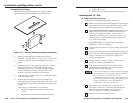
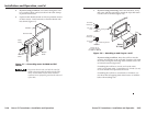
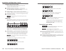
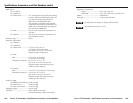
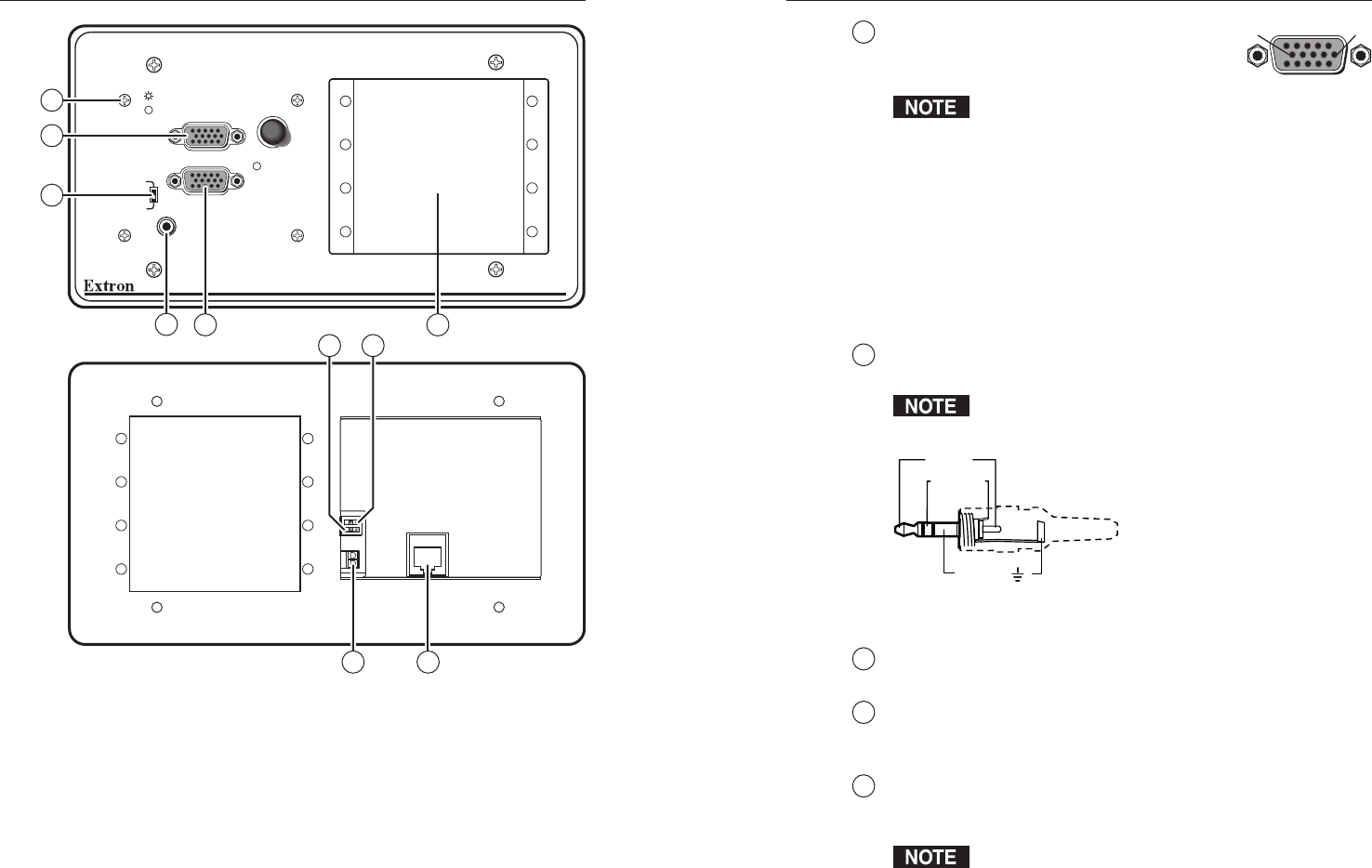
Figure 2-16 — Installation features, TP T 468
Transmission of component video, S-video, or composite video
on the computer video input requires that internal jumpers
(TP T 15HD A and TP T 15HD AV) or a DIP switch (TP T 468) be
reconfigured. See “Video jumpers,” or “Video DIP switch,”
earlier in this chapter.
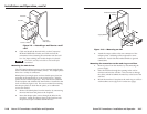
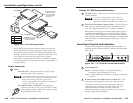
1
Computer Input connector — Connect a
computer video source to this 15-pin HD
female connector.
Input only sync signals, no video
signals, on the sync pins (pins 13 and 14).
For component video, use the R (R-Y) and R return pins
(pins 1 and 6), G (Y) and G return pins (pins 2 and 7),
and B (B-Y) and B return pins (pins 3 and 8).
For S-video, use the R, R return (C-chroma), G, and G
return (Y-luma) pins.
For composite video, use the G pin and the associated
return pin. For additional genlocked video signals, use
the R, B, and associated return pins.
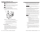
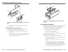
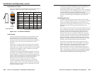
2
Audio input connector — Connect PC audio to this 3.5 mm,
stereo jack. Wire the male plug as shown in figure 2-17.
Input only analog, line level, audio signals on the audio
input connector.
Sleeve ( )
Ring (R)
Tip (L)
Figure 2-17 — Audio input wiring
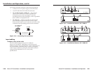
3
Buffered Local Monitor output connector — Connect a local
monitor video cable to this 15-pin HD female connector.
4
ID bit switches (TP T 15HD A and TP T 15HD AV) — If a local
monitor is installed, set both switches to off. If no local monitor
is installed, set both switches to on.
5
DDSP switch — This switch turns on Digital Display Sync
Processing, disabling sync processing for LCD projectors and
other displays that cannot tolerate processed sync.
DDSP disables the horizontal shift control.
51
15 11
610
Female
2-22 2-23