


Extron TP Transmitters • Installation and Operation
Extron TP Transmitters • Installation and Operation
Installation and Operation, cont’d
2-18
Installation
Cable
Cable
Clamp
TP T 468
MONITOR
H. SHIFT
AUDIO
MIN/MAX
MONITOR
MONITOR
TP T 468
INPUT
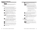
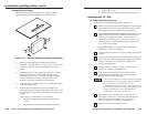
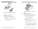
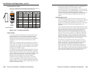
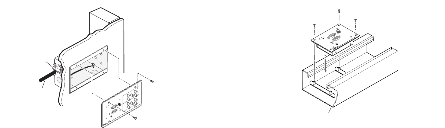
Figure 2-11 — Mounting the transmitter to the wall
box
4. Reconnect the power supply and restore power to the
equipment.
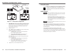
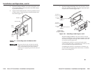
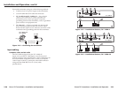
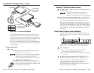
Installing the Euro Channel transmitter
Once the EC transmitter has been cabled and tested, the
transmitter can be installed in the Euro Channel.
1. Remove power from the interface by disconnecting the
power supply.
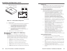
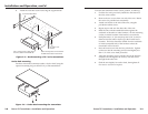
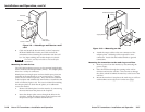
2. Mount the interface to the Euro Channel by attaching the
faceplate to the two mounting brackets using the four #4-
40 mounting screws (figure 2-12).
Euro Channel
TP T 460
INPUT
MONITOR
H. SHIFT
MIN/MAX
AUDIO
N
O M
O
N
IT
O
R
M
ON
IT
O
R
Figure 2-12 — Mounting the transmitter in a Euro
Channel
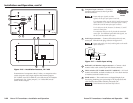
Grounding the transmitter
RGB and computer video transmitters may need to be grounded
to ensure that the video and audio are not degraded. The
TP T 15HD A, TP T 15HD AV, and TP T 468 may require
grounding if all of the following conditions are true:
• The signal source is a laptop computer.
• No local monitor is connected.
• A local power supply is not being used.
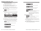
Grounding may also be required if there is no common ground
in the power distribution system.
Indications that grounding may be required include:
• The receiver’s Power LED is lit amber when a connection
is made to the transmitter.
• The receiver is in auto mode and its Manual/Auto LED
flashes.
• The receiver is in manual mode and an image appears
only when the Peaking adjustment is at the minimum
level. Additionally, the image may be overpeaked with
horizontal streaking to the right of displayed information.
• No audio, or distorted and noisy audio, is heard.
2-19