


TP T 15HD 45 and TP T A 45 • Installation
TP T 15HD 45 and TP T A 45 • Installation
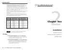
Installation, cont’d
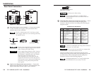
Front Panel Connectors and Indicators
AUDIO
INPUT
COMPUTER
INPUT
1
2
3
1
TP T 15HD 45
TP T A 45
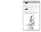
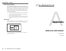
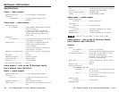
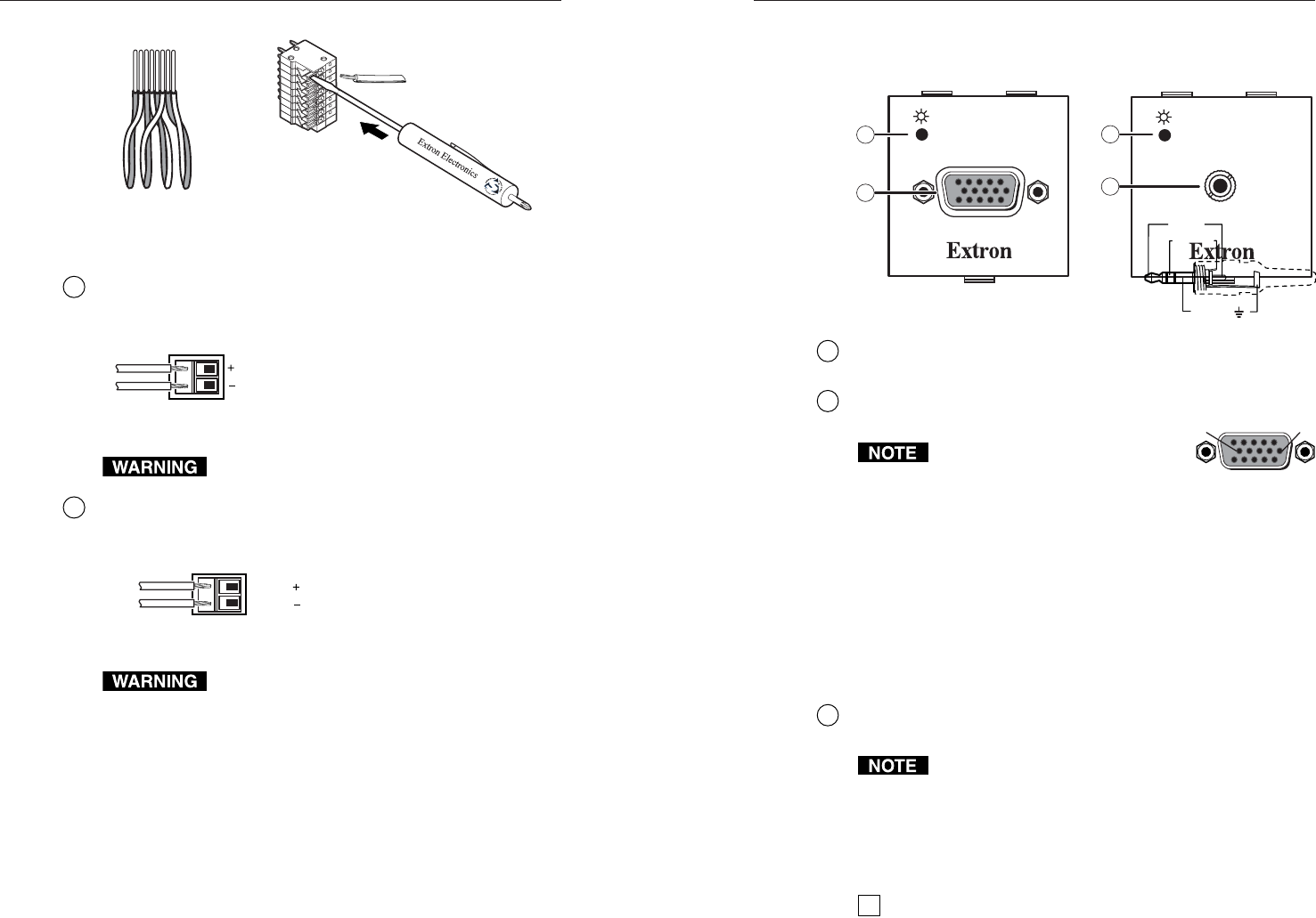
Figure 2-2 — Front panel views
1
Power LED indicator — The LED lights green whenever power
is applied.
2
15-pin HD video input connector — Connect computer video
input.
Input only sync signals, no video
signals, on the sync pins, 13 and 14.
For component video, use the R (R-Y)
and R return pins (pins 1 and 6), G
(Y) and G return pins (pins 2 and 7), and B (B-Y) and B
return pins (pins 3 and 8).
For S-video, use the R, R return (C-chroma), G, and G
return (Y-luma) pins.
For composite video, use the G pin and the associated
return pin. For additional genlocked video signals, use
the R, B, and associated return pins.
The TP T 15HD 45 and TP T A 45 are only compatible
with the RGBHV and RGBS VTR series of receivers.
3
3.5 mm stereo mini jack input — Connect unbalanced audio to
this stereo jack. Wire the male plug as shown below.
Input only analog and line level audio signals on this
connector.
Cabling and Setup
To install the TP T 15HD 45 and TP T A 45 models, follow these
steps:
1
Turn all of the equipment off and, if applicable, disconnect
it from the power source.
2-52-4
1
1&2
3&6 4&5
7&8
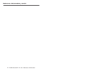
2345678
Twisted Wire Pairs
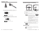
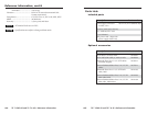
3
Power input captive screw connector — Connect power input
cables to the 2-pole female direct insertion captive screw
connector.
12 VDC
.5A MAX.
Power Input Captive Screw
Direct Insertion Connector
-
+
Remove power before wiring.
4
Digital audio output captive screw connector — Connect the
digital audio output cables to the 2-pole female direct insertion
captive screw connector.
Digital Audio Output
Captive Screw Direct Insertion Connector
AUDIO
AUDIO
-
+
Remove power before wiring.
Sleeve ( )
Ring (R)
Tip (L)
51
15 11
610
Female