


TP T 15HD 45 and TP T A 45 • Installation
TP T 15HD 45 and TP T A 45 • Installation
Installation, cont’d
-
+
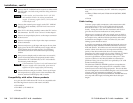
Digital Audio Input Captive Screw
Direct Insertion Connector
+
AUDIO
-
AUDIO
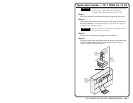
Remove power before wiring.
The wire gauge should be 14 -22 AWG and the
maximum distance between the modules should not
exceed 25 feet.
2
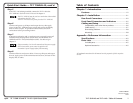
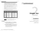
Video and audio output 8-pin spring force connector — Attach
a UTP cable from a TP receiver to the 8-pin spring force
connector. Wire this connector according to the following pin
assignment table.
Twisted Pair Pin Assignments
Pin Signal
1
2
3
4
5
6
7
8
red / vertical sync +
red / vertical sync - green orange
digital audio + white-orange white-green
green + blue blue
green - white-blue white-blue
digital audio - orange green
blue / horizontal sync + white-brown white-brown
blue / horizontal sync - brown brown
TIA/EIA T-568-A
Wire Color
white-green white-orange
TIA/EIA T-568-B
Wire Color
T-568-A is recommended when using Extron Enhanced
Skew-Free™ A/V UTP cable.
CAUTION
Do not connect the transmitter to a computer data
or telecommunications network.
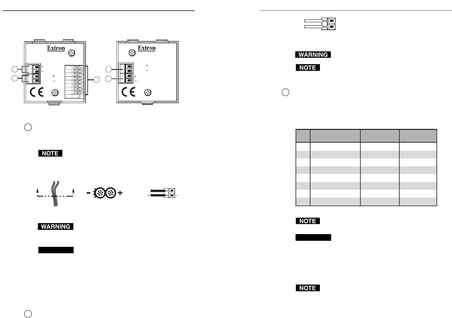
Using the included tweeker tool and observing the correct
wiring colors in the previous table, insert the stripped wire ends
(see note below) of the twisted pairs into the spring force
connector, as shown in the following diagram.
Strip approximately 0.43" (1.1 cm) of insulation from
each individual wire on one end of a TP cable.
2-3
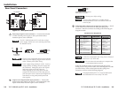
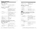
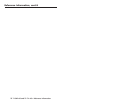
Rear Panel Connectors
AUDIO
AUDIO
12 VDC
.5A MAX.
OUTPUT
12345678
TP T 15HD 45
TP T A 45
AUDIO
AUDIO
12 VDC
.5A MAX.
3
1a
1b
2
TP T 15HD 45
TP T A 45
4
Figure 2-1 — Rear panel views
1a
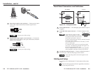
Power input captive screw connector — Connect the included
12 VDC external power supply to the 2-pole female direct
insertion captive screw connector.
The TP T 15HD 45 and the TP T A 45 share a single
power supply. Neither one can be remotely powered by
the attached receiver.
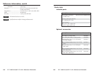
Power Supply
Output Cord
Captive Screw
Direct Insertion Connector
12 VDC
.5A MAX.
AA
SECTION A–A
+
+
The two power supply leads must be kept separated
while the power supply is plugged into an electrical
outlet. Remove power before wiring.
CAUTION
Power supply voltage polarity is critical. Incorrect
voltage polarity can damage the power supply and
the transmitter. Identify the power cord negative
lead by the ridges on the side of the cord.
When stripping the wire ends, please note that
stripped wire ends that are too short may pull out
from the captive screw connector and stripped wire
ends that are too long could possibly touch and
short together.
1b
Captive screw digital audio input connector — Connect the
digital audio input cables from the TP T A 45 (if installed) to the
2-pole female direct insertion captive screw connector.
Installation
2-2