


2
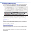
SMD101 • Setup Guide (Continued)
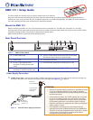
Output Connections
b HDMI output – Connect an HDMI (or DVI with suitable adapter) display device to the HDMI output connector. The EDID of a
connected display is read and the output automatically congured. For non-standard displays or devices, see the SMD101
User Guide for additional output resolutions and format settings.
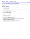
c Audio output – Connect a balanced or unbalanced stereo (or dual mono) line level audio device to this 5-pole 3.5 mm
captive screw connector (see figure 1,
c
on the previous page). Wire the connector as shown in gure 3, below.
ATTENTION: For unbalanced audio, connect the sleeves to the ground contact.
DO NOT connect the sleeves to the negative (–) contacts.
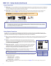
Balanced Audio Output
Tip
Ring
Tip
Ring
LR
Slee
ves
Unbalanced Audio Output
Tip
Tip
LR
Sleeves
Do not tin the wires!
Figure 3. Audio Output Captive Screw Connector Wiring
NOTES:
• The length of the exposed wires in the stripping process is critical. The ideal length is 3/16 inch (5 mm). If longer,
the exposed wires may touch, causing a short circuit between them. If shorter, the wires can be easily pulled out
even if tightly fastened by the captive screws.
• Do not tin the wires. Tinned wire does not hold its shape and can become loose over time.
Control System Connections
The SMD101 can be congured and controlled from the RS-232 port or the front panel mini-type B USB cong port using
DataViewer, or from the LAN port using a standard web browser. Since the LAN port must be connected for streaming source
input, Extron recommends also using it for conguration and remote control of the SMD101.
d IR In – Connect an (optional) IR receiver to this 3-pole 3.5 mm captive screw connector to extend the range of the IR hand
control. The optional IR hand control provides access to the on screen menus for conguration and direct control over
playback.
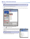
e RS-232 — Connect the host RS-232 cable to the rear panel (see right) with a 3-pole
captive screw connector for bi-directional (±5V) serial host control or IPpass-through.
The default protocol for this port is 9600 baud rate, no parity bit, 8 data bits, 1 stop bit,
and no flow control (handshaking).
f Reset button and LED — The SMD101 has three reset modes to return user-dened
conguration settings or all settings back to factory defaults. The LED indicates the
desired reset mode, and provides the reset status during the reset operation. For
information on using the reset mode, see the SMD 101 User Guide.
g RJ-45 Ethernet connector (LAN) — Use a standard Ethernet cable to connect to a
network (see right). The table at right has the default network settings.
NOTE: To connect the SMD101 directly to a computer Ethernet port, use a
crossover Ethernet cable.
The ACT (amber) LED indicator on the LAN connector blinks in a pattern to indicate the
connected network speed.
• Three blinks, pause — 1 Gigahertz
• Two blinks, pause — 100 Megahertz
• One blink, pause — 10 Megahertz
USB — Connect the host USB port to the front panel cong port (see figure 4,
e
on the next page), using a typeA to
minitypeB USB cable.
IP Address: 192.168.254.254
Subnet Mask: 255.255.0.0
Default Gateway: 0.0.0.0
DHCP: OFF
Tx Rx G
SG
RS-232
RESET
IR IN
LAN
Ground
Receive
Transmit
Connected RS-232
Device Pins
+
S
IR
Transmitter
G