


RGB A OUT
RGB B OUT
INPUT 2
INPUT 1
REMOTE
CONTACT
PIN 1 — IN 1
PIN 4 — IN 2
PIN 5 — GND
MONITOR OUT
RGB A OUT
RGB B OUT
POWER
12V
3A MAX
1B
1A
I
N
P
U
T
S
2B
2A
RGB
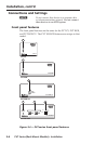
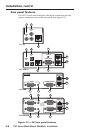
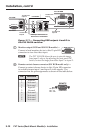
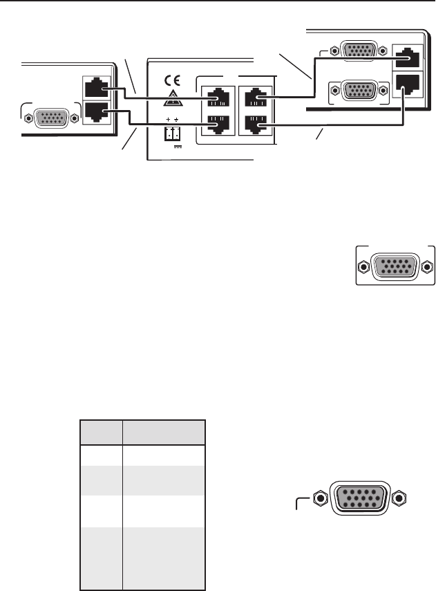
RGB Input Connectors on
Rear Panel of PVS 204SA
TP Cable from
output A
Rear Panel
Rear
Panel
PVT SW RGB
PVT RGB
TP Cable from
output B
TP Cable from
output B
TP Cable from
output A
PVS 204SA
MONITOR OUT
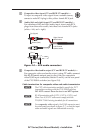
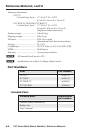
Figure 2-11 — Connecting RGB outputs A and B to
the PVS 204SA switcher
g
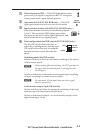
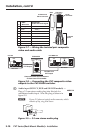
Monitor output (RGB and SW RGB models) —
Connect a local monitor device to this 15-pin HD
connector to view the video input.
N
The PVT SW RGB allows the user to view the image
from input 1 only or, by adjusting the front panel DIP
switch, to view the image from either input 1 or input 2.
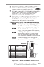
h
Remote contact closure connector (SW RGB model only) —
Connect a contact closure device to this 15-pin HD connector
to switch between input 1 and input 2 video signals. The
connector has the pin assignments as shown in the table below.
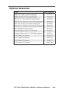
Pin Function
1 Input #1
2 Not used
3 Not used
4 Input #2
5 Ground
6 Not used
7 Not used
8 Not used
9 Not used
PVT Series (Rack Mount Models) • Installation
MONITOR OUT
2-12
Installation, cont’d
REMOTE
CONTACT
PIN 1 — IN 1
PIN 4 — IN 2
PIN 5 — GND