


MTP R 15HD RSA D • Installation and Operation
Installation and Operation, cont’d
2-12
MTP R 15HD RSA D • Installation and Operation
2-13
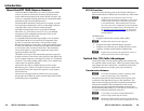
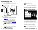
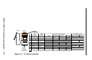
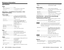
Audio/RS-232 cable termination
Receive (Rx)
Transmit (Tx)
Ground ( )
Bidirectional
Mono Audio Output
RS-232 Output
Tip
Ring
Sleeve
RxTx
RS-232
Device
Ground ( )
Receive (Rx)
Transmit (Tx)
RxTx
Do not tin the wires!
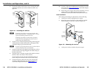
Figure 2-7 — Captive screw audio/RS-232 connector
wiring
C
The length of the exposed (stripped) portion of
the copper wires is important. The ideal length
is 3/16” (5 mm). Longer bare wires can short
together. Shorter bare wires are not as secure in the
direct insertion connectors and could be pulled out.
Receiver Considerations
N
Each transmitter in a system requires a separate receiver.
N
Up to seven standard receivers (MTP RL 15HD RS
and MTP RL 15HD A, with or without SEQ) can be
connected in series between the transmitter and the MTP
R 15HD RSA D. This daisy chain is accomplished using
the standard receivers' Buffered Output connectors.
The total distance from the transmitter’s TP output
to the last receiver in the chain should not exceed the
recommended distance for the resolution being used.
N
The receivers' buffered outputs do not provide
pre-peaking control. The total recommended distance
for an entire daisy chain is the same as for a single
transmitter and receiver. The transmitter's Pre-Peak
switch has the same effect on the recommended
transmission distance for a daisy chain as for a single
transmitter and receiver.
N
See the recommended transmission ranges in the table
on page 1-4. The recommendations in the table apply
equally for a single transmitter and receiver and for a
transmission daisy chain. For example, the maximum
suggested range for 1024 x 768 video is 300’ with
Pre-Peak off and 500’ with Pre-Peak on for either one
transmitter and one receiver or one transmitter and three
daisy-chained receivers.
N
For daisy-chained units, the first receiver in the chain
must be at least 100’ from the transmitter when the
Pre-Peak switch is on.
N
For daisy-chained units, any receiver in the chain closer
than 350’ may experience some form of over-peaking
when the Pre-Peak switch is on.
Skew Delay Compensation
CAT 5/5e/6 TP cable can lead to registration errors between the
red, green, and blue video signals. Pair skew can be measured
with test equipment or identied by viewing a crosshatch test
pattern with a critical eye to determine if either the red, green,
or blue video image leads (appears to the left of) the other two
video images.
Try using the following methods to minimize or eliminate pair
skew:
• Switch to Extron’s Enhanced Skew-Free A/V UTP cable.
• Add a skew compensation cable equal to the length of
pair skew to the receiver’s output.
• Install an SEQ 100 15HD Skew Equalizer on the receiver’s
video output and adjust the skew for the leading video
image.