


MTP R 15HD RSA D • Installation and Operation
Installation and Operation, cont’d
2-6
MTP R 15HD RSA D • Installation and Operation
2-7
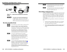
Connections and Settings
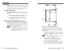
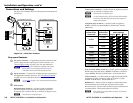
See gure 2-4 to identify the rear and front panel connections on
the receiver.
MTP 15HD RSA D Rx Rear Panel
MTP 15HD RSA D Rx Front Panel
INPUT
H SYNC +
V SYNC +
C SYNC
SOG
VIDEO
Bi-RS232
H SYNC +
V SYNC +
C SYNC
SOG
VIDEO
Bi-RS232
OUTPUT
PEAKING
LEVEL
AUDIO RS-232
Tx Rx
2
1
3
4
6
5
7
Figure 2-4 — Receiver’s features
Rear panel features
a
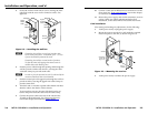
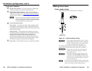
DC power connector — If applicable, plug the external 12 VDC
power supply into this 2-pole captive screw connector. See
"Power supply wiring" on page 2-9 to wire the connectors.
N
The remote power capabilities available with certain
MTP models are not supported by this unit; the
transmitter and receiver both must be powered.
b
Input connector — Connect the TP cable from the transmitter to
this pigtail RJ-45 female connector. See “TP cable termination”
on page 2-10 to wire the RJ-45 connectors.
N
See the table on page 1-4 for recommended transmission
ranges.
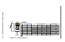
c
DIP switches
Horizontal Sync switch (1) — Set this switch on (right) for
positive horizontal sync (or positive composite sync if the
Composite Sync switch is also on) or off (left) for negative sync.
N
Most devices use negative sync.
Vertical Sync switch (2) — Set this switch on (right) for positive
vertical sync or off (left) for negative sync.
N
Most devices use negative sync.
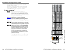
N
Set the Composite Sync, SOG, and Video DIP switches
as shown in the table below for the various input and
output video formats.
Composite Sync switch (3) — Set this switch on (right) for
RGBS or off (left) to output RGBHV or RGsB video. See the
table below.
Output signal
format from
the receiver
Input signal
format to the
transmitter
Receiver's DIP
switch settings
C Sync SOG Video
RGBHV
RGBSRGBHV
RGsB
RGBS
RGsB
RGsB
Component
S-video
Composite
RGBS
RGsB
RsGsBsRsGsBs
Component
S-video
Composite
Sync-on-Green (SOG) switch (4) — Set this switch on (right) for
RGsB video (when the input is RGBHV or RGBS) or off (left) to
output RGBHV, RsGsBs, or RGBS video. See the table above.
Video switch (5) — Set this switch on (right) for RsGsBs, RGsB,
component/S-video/composite video or off (left) to output
RGBHV or RGBS video. See the table above.
BI-RS232 (6) — Set this switch on (right) to select bidirectional
communications when serial data is present on the audio/
RS-232 wire pair. Set the switch off (left) to select unidirectional
communications. The default position is off (left).
N
This switch is ignored if audio is present on the audio/
RS-232 wire pair.