


HDMI 201 Tx/Rx • Installation and Operation
Installation and Operation
HDMI 201 Tx/Rx • Installation and Operation
2-2
2-3
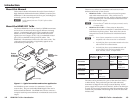
Mounting the Tx/Rx
C
Installation and service must be performed by
authorized personnel only.
Non-Decora unit mounting
The 1" high, quarter rack width HDMI 201 (non-Decora)
transmitters and receivers can be placed on a tabletop, mounted
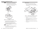
on a rack shelf, or mounted under a desk or tabletop. The
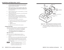
receiver can be mounted on a projector bracket.
Tabletop placement
Affix the four included rubber feet to the bottom of the unit and
place it in any convenient location.
Rack mounting
UL requirements
The following Underwriters Laboratories (UL) requirements
pertain to the installation of the transmitter or receiver into or
onto a rack (figure 2-1).
1. Elevated operating ambient — If the equipment is
installed in a closed or multi-unit rack assembly, the
operating ambient temperature of the rack environment
may be greater than room ambient. Therefore, consider
installing the equipment in an environment compatible
with the +122 °F (+50 °C) maximum ambient temperature
(Tma) specified by Extron.
2. Reduced air flow — Installation of the equipment in a rack
should be such that the amount of air flow required for
safe operation of the equipment is not compromised.
3. Mechanical loading — Mounting of the equipment in
the rack should be such that a hazardous condition is not
achieved due to uneven mechanical loading.
4. Circuit overloading — Consideration should be given to
the connection of the equipment to the supply circuit and
the effect that overloading of the circuits might have on
overcurrent protection and supply wiring. Appropriate
consideration of equipment nameplate ratings should be
used when addressing this concern.
5. Reliable earthing (grounding) — Reliable earthing
of rack-mounted equipment should be maintained.
Particular attention should be given to supply connections
other than direct connections to the branch circuit (such as
the use of power strips).
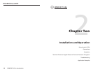
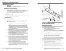
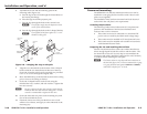
(2) 4-40 x 3/16"
Screws
Use 2 mounting holes on
opposite corners.
VersaTools Rack Shelf
1/4 Rack Width Front
False Faceplate
Figure 2-1 — Mounting the transmitter or receiver
unit on a VersaTools rack shelf
Rack mounting instructions
For optional rack mounting, mount the transmitter or receiver
on any of the following rack shelves:
• RSF 123 3.5" deep 1U VersaTools
®
rack shelf kit
(part #60-190-20) (figure 2-1)
• RSB 123 3.5" deep 1U VersaTools rack shelf (part #60-604-20)
• RSU 126 6" deep 1U universal rack shelf kit
(part #60-190-10)
• RSB 126 6" deep 1U basic rack shelf (part #60-604-10)
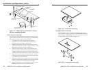
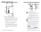
• RSU 129 9.5" deep 1U universal rack shelf kit
(part #60-190-01) (figure 2-2 on the next page)
• RSB 129 9.5" deep 1U basic rack shelf (part #60-604-01)
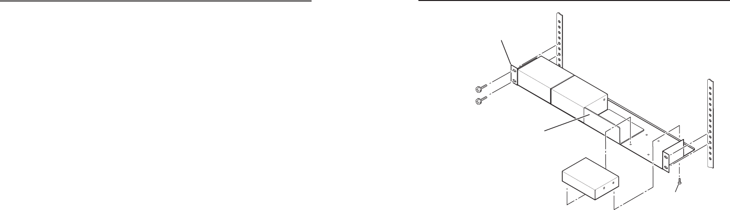
On the non-VersaTools rack shelves, the transmitter or receiver
unit can be mounted in the front or the rear of the rack.
1. Remove the feet from the bottom of the transmitter or
receiver unit, if they are installed.
2. Mount the transmitter or receiver unit using two
4-40 x 3/16" screws in opposite (diagonal) corners to
secure the transmitter or receiver to the shelf.
3. Install false faceplate(s) or other unit(s) to the rack shelf.