


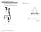
HDMI 201 Tx/Rx • Installation and Operation
Installation and Operation, cont’d
2-24
HDMI 201 Tx/Rx • Installation and Operation
2-25
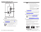
Terminating shielded cable
N
The transmitter and receiver pair works with unshielded
twisted pair (UTP) or shielded twisted pair (STP) cables;
but, to ensure FCC Class A and CE compliance, STP
cables are recommended.
The Tx/Rx includes four shielded RJ-45 connectors and a length
of self-adhesive shielded tape that you can use to make the STP
cables that connect the transmitter and receiver.
N
Extron supplies the connectors and the shielded tape.
You must supply the CAT 5, 5e, 6, or 7 STP cable.
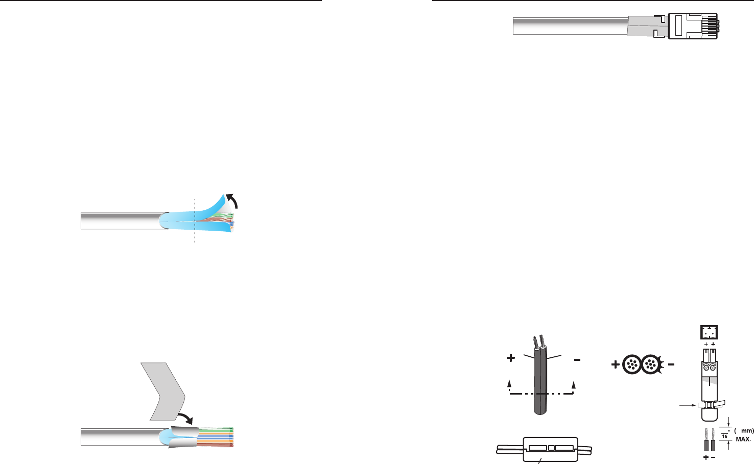
Terminate the STP cable as follows:
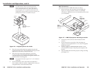
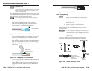
1. Peel back the cable shielding (figure 2-21) from the
end of the cable the length of the RJ-45 connector body
(approximately 7/8" [2.2 cm]) and fold it back.
Peel back shield and
fold back.
Figure 2-21 — Peeling back the cable shielding
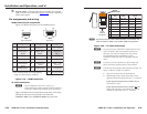
2. Cut away and discard the clear cellophane inner wrapper
from the end of the cable back to the folded-over cable
shielding.
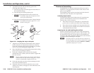
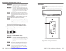
3. Peel the backing off the self-adhesive shielded aluminum
tape and wrap it around the folded-over cable shielding,
slightly overlapping the beginning of the tape
(figure 2-22).
Aluminum Tape
Wrap tape around folded foil shielding.
Slightly overlap.
Cut and save the excess tape
for other connectors.
Figure 2-22 — Wrapping the shielded tape
4. Cut the unused portion of the shielded tape and retain for
shielding other RJ-45 connectors.
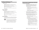
5. Crimp the RJ-45 cable in the normal manner, folding the
tangs at the end of the connector over the shielded tape
(figure 2-23).
Crimped Connector
Figure 2-23 — Crimped RJ-45 connector
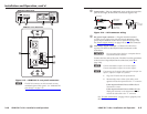
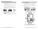
Power supply wiring
N
• Only one power supply is required. A single power
supply connected to either unit in the pair powers
both units.
• A single power supply is included with systems
packaged as a pair.
• A power supply is also included with each
individually-packaged transmitter.
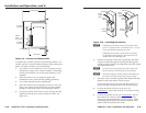
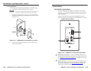
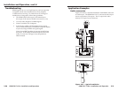
Figure 2-24 shows how to wire the connector for non-Decora
and Decora units.
C
Power supply voltage polarity is critical. Incorrect
voltage polarity can damage the power supply and
the transmitter or receiver. Identify the power cord
negative lead by the ridges on the side of the cord
(figure 2-24).
To verify the polarity before connection, plug in the power
supply with no load and check the output with a voltmeter.
Power Supply
Output Cord
Orange Captive
Screw
Connector
Non-Decora units
SECTION A–A
Ridges
Smooth
A A
Ferrite Bead
DC Power Cord
(between power supply
and DVI unit
power connector)
Tie Wrap
3
5
Figure 2-24 — Power connector wiring