


HDMI 201 Tx/Rx • Installation and Operation
Installation and Operation, cont’d
2-26
HDMI 201 Tx/Rx • Installation and Operation
2-27
W
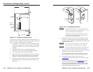
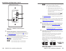
The two power cord wires must be kept separate
while the power supply is plugged in. Remove
power before wiring.
C
The length of the exposed (stripped) copper wires
is important. The ideal length is 3/16" (5 mm).
Longer bare wires can short together. Shorter wires
are not as secure in the connector and could be
pulled out.
N
Do not tin the power supply leads before installing in
the direct insertion connector. Tinned wires are not as
secure in the connectors and could be pulled out of the
connector.
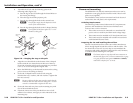
Non-Decora units only — Use the supplied tie-wrap to strap
the power cord to the extended tail of the connector.
N
Your transmitter/receiver pair may have shipped with a
blue captive screw connector. This blue connector can be
plugged into either a blue or an orange power receptacle.
The blue connector does not have the extended tail or the
included tie-wrap.
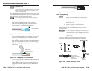
Snap the provided ferrite bead onto the DC power cable,
between the power supply and the HDMI unit’s connector.
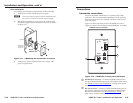
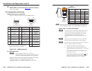
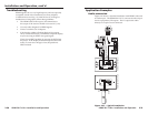
RS-232 connector wiring
Figure 2-25 shows how to wire the RS-232 connector for non-
Decora and Decora units.
Ground
Receive
Transmit
Connected RS-232
Device Pins
Tx/Rx
Pins
Rx
Tx
Figure 2-25 — RS-232 connector wiring
C
The length of the exposed (stripped) copper wires
is important. The ideal length is 3/16" (5 mm).
Longer bare wires can short together. Shorter wires
are not as secure in the connector and could be
pulled out.
N
Do not tin the power supply leads before installing in
the connector. Tinned wires are not as secure in the
connectors and could be pulled out of the connector.
N
The RS-232 connector can also transmit one-way
modulated infrared (IR) signals. See "Modulated IR
pass through" on page 2-32.
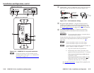
Operation
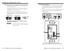
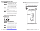
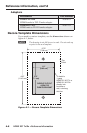
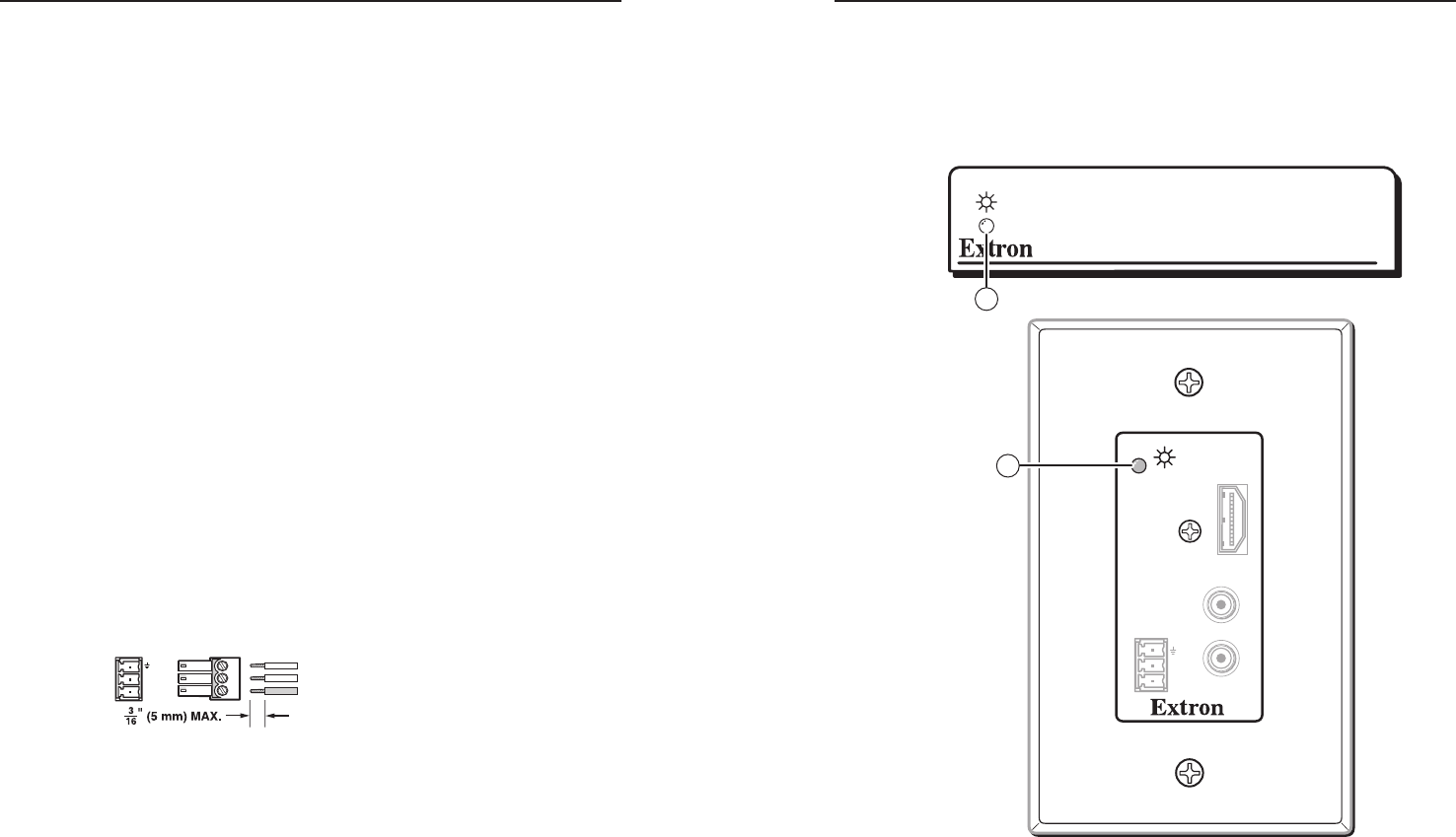
Figure 2-26 shows the power indicator on the non-Decora and
Decora models.
N
Two units are shown. All transmitter and receiver
models have power indicators in the locations shown.
HDMI 201
INPUT
Rx
Tx
RS-232
PASS THRU
AUDIO-R
HDMI
AUDIO-L
1
HDMI 201 Tx and HDMI 201 Rx Front Panel
HDMI 201 A D Tx and HDMI 201 A D Rx Front Panel
1
Figure 2-26 — Front panel indicators