


FOX HD-SDI • Installation and Operation
Installation and Operation, cont’d
2-12
FOX HD-SDI • Installation and Operation
2-13
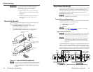
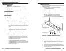
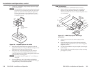
Rx — If the FOX HD-SDI is configured as a bidirectional
transceiver or as a receiver, for one-way communications
from the transmitting unit, connect a fiber optic cable to the
Optical Rx connector.
If the FOX HD-SDI is configured as a bidirectional transceiver,
connect the free end of this fiber optic cable to the Optical Tx
connector on the transmitting FOX HD-SDI.
If the FOX HD-SDI is configured as a receiver, connect the
free end of this fiber optic cable to the Optical Tx connector
on the next FOX HD-SDI in the daisy chain.
d
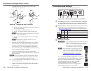
Buffered Outputs connectors — In any FOX HD-SDI
configuration, connect a digital display to these BNC
connectors. See "Transceiver configurations" on page 1-3 for
more details.
If the FOX HD-SDI is configured as a bidirectional transceiver,
the video is output on both connectors 1 and 2 and is the video
signal sent from the other transceiver.
If the FOX HD-SDI is configured as a receiver, the video
is output on connector 2 only and is the video sent by the
transmitting unit.
If the FOX HD-SDI is configured as a transmitter, the video is
output on both connectors 1 and 2 and is looped through from
the same transceiver's HD/SDI Input connector, item
a
.
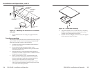
e
Power connector — Plug the included external 12 VDC
power supply into this 2-pole captive screw connector.
See “Power supply wiring”, on the next page, to wire the
connector.
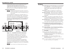
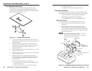
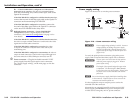
Power supply wiring
Figure 2-10 shows how to wire the power connector.
Power Supply
Output Cord
Captive Screw
Connector
SECTION A–A
Ridges
Smooth
A A
Tie Wrap
3
5
Figure 2-10 — Power connector wiring
C
Power supply voltage polarity is critical. Incorrect
voltage polarity can damage the power supply
and the FOX HD-SDI. Identify the power cord
negative lead by the ridges on the side of the cord
(figure 2-10).
To verify the polarity before connection, plug in the power
supply with no load and check the output with a voltmeter.
W
The two power cord wires must be kept separate
while the power supply is plugged in. Remove
power before wiring.
C
The length of the exposed (stripped) copper wires
is important. The ideal length is 3/16" (5 mm).
Longer bare wires can short together. Shorter wires
are not as secure in the connectors and could be
pulled out.
N
Do not tin the power supply leads before installing them
in the connector. Tinned wires are not as secure in the
connectors and could be pulled out.
Use the supplied tie-wrap to strap the power cord to the
extended tail of the connector.
Alternatively, an optional Extron PS 123 Universal 12 VDC
Power Supply, part #60-814-01, can power multiple Extron
12 VDC devices using only one AC power connector.