


2-5DVS 204 • Installation and Operation
4
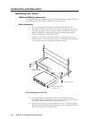
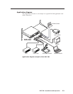
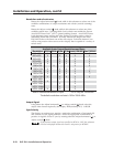
Video input 3: S-video — Connect an S-video signal to this 4-pin
mini-DIN female connector.
5
SDI (serial digital interface) input connector — Connect an SDI
signal to this female BNC connector.
Only the DVS 204 D and DVS 204 D 12V models have an SDI connector.
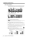
6
Video input 4: RGB pass-through, RGBS, or RGBcvS —
Connect an RGB pass-through (RGBHV, RGBS, RGsB), RGBS,
or RGBcvS video signal to this 15-pin HD connector. The
pass-through signals are not scalable.
Equipment following the SCART interconnection standard
may be connected to the RGBcvS input cabling configuration.
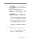
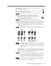
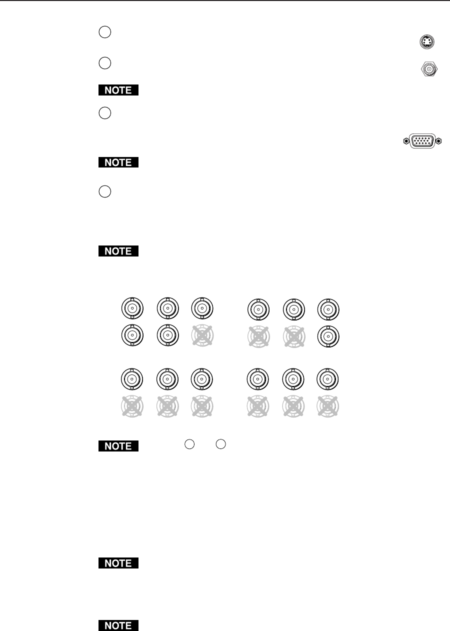
7
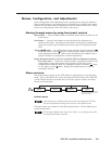
RGB (RGBHV, RGBS, RGsB) or HD component (R-Y, Y, B-Y) video BNC
output — Connect coaxial cables from a display device to these BNCs for a
scaled or pass-through RGB or a scaled component video output. The
output can be scaled to 56 different output rates. The scaled inputs (1-3) are
output, as shown below.
The default for the “H” BNC connector is always horizontal sync. See the
following section “RGB pass-through”, for the only exception to this rule.
H
R
/R-Y
V
G
/Y
S
B
/B-Y
OUTPUTS
H
R
/R-Y
V
G
/Y
S
B
/B-Y
OUTPUTS
H
R
/R-Y
V
G
/Y
S
B
/B-Y
OUTPUTS
H
R
/R-Y
V
G
/Y
S
B
/B-Y
OUTPUTS
Component Video (R-Y, Y, B-Y)
RGBHV*
RGBS
RGsB
Outputs
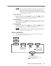
7
and
8
are both buffered and can be connected simultaneously
to two different displays. For RGB inputs, the output signal’s sync format is
based on the format of the incoming RGB signal. For all other types of
inputs, the user selects the output sync format. The sync format will be the
same for both outputs.
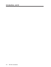
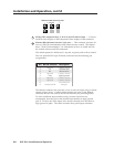
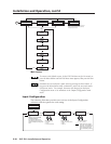
RGB pass-through — An RGB pass-through signal with composite sync
(“RGB” is selected for input 4; see the Input Configuration section in this
chapter) will always output composite sync through the “H” BNC output
connector, as shown in the following illustration.
If both an RGB pass-through signal with composite sync and a scaled video
input (1-3) are output as RGBS, the H Format must be set to “HV”
(composite sync). This will cause the scaled video input to output composite
sync on the same connector (the “H” BNC) as the pass-through signal
instead of the “S” BNC. See the H Format section in this chapter.
For scaled inputs on input 4 (RGBS or RGBcvS), the H Format will not
have to be set to “HV” since those inputs will be output like inputs 1-3, as
shown in the previous connection diagram.
3
S-VIDEO
4
RGB
PASS - THRU/
RGBS/RGBcvS
SDI