


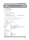

15 Ethernet interface
Page18
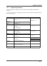
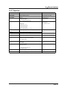
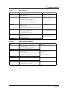
14.5.11.Launchingplottingandrecording
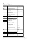
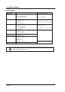
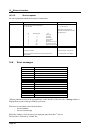
14.5.12.Diagrams
HEADERPARAMETERSEXAMPLES
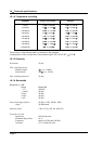
RECo
rd
P1RECORDON
StartorStop
ofplottinginDIRECTmode,
orrecordinginothermodes.
P1=ON:start
OFF:stop
TRIG:forcingof trigger
TRIGREC: forcingofmemory triggerin DIRECTmode
RECord ?
Returns thecommandandtheratioof theMEMORYrecording
In DIRECTmode, theplottingwillbegan
afterstart triggeristrue
The triggeringcanbe forced with
RECORDTRIGforstartand RECORD
OFFforstop
HEADERPARAMETERSEXAMPLES
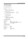
G
R
ID
P1,P2
Defines thediagrams
P1= Numberofdiagram
GRID ?
Returns thedefinitionofalldiagrams
G
R
I
D
:
L
O
G
P
1
,
P
2
,
P3
Defines thediagrams forlogicchannels
P1=Numberoflogicchannels
P2=Heighoflogicchannels
P3=UPor DOWN:positionoflogicchannels
GRID:LOG ?
Returns thedefinitionoflogicdiagram
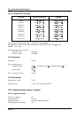
G
R
I
D
:
L
E
N
G
th
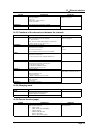
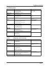
P1,P2,P3GRID:LENG1,0,100
DefineseachdiagramDiagram1from0 to100mm
P1=numberofthediagram
P2=minvalue(0 tomax)
maxis250or200(dependofinstrument)
P3=maxvaluemax(0 tomax)
GRID:LENGth ?
Returns thedefinitionofdiagrams
G
R
I
D
:
C
H
A
n
n
el
P1,P2,P3GRID:CHAA4,3,2
Defines thepositionofachannelChannelA4indiagram3witha widthof
2
P1=Numberofthechannel
P2=Numberofdiagram :from1 toMax
P3=drawingthickness :1to 8
GRID:CHAnnel ?
Return thedefinitionofCHANNEL
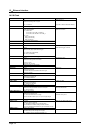
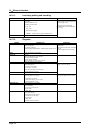
COLO
R
P1,P2,P3CHANA2,COLOR100,100,100
Colorof CHANNEL
P1=redvalue(from0 to100)
P2=greenvalue
P3=bluevalue
D
E
FL
OG
P1,P2,P3,P4,P5
Defineslogicchannels
P1=Numberofthelogicchannel
P2=redvalue( from0to100)
P3=greenvalue
P4=bluevalue
P5=Nameof thelogicchannel
GRID:LOG50,5,UP;:GRID
2,SEPLOGON
L
o
g
i
c
c
h
a
n
n
e
ls
a
r
e
a
t
t
h
e
t
o
p
,
w
i
t
h
h
e
i
g
h
t
of50mm.
Wehave2diagramsof100mmeach.
P2=SEPLOGONouSEPLOGOFF : separatedlogicchannelsornot