


5
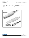
MODEL 396P and 396PVP SECTION 2.0
INSTALLATION
SECTION 2.0
INSTALLATION
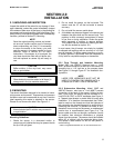
2. Do not install the sensor on the horizontal. The
sensor must be 10° off the horizontal to ensure
accuracy.
3. Do not install the sensor upside down.
4. Air bubbles may become trapped in the sensor end
between the glass bulb and the sensor body. This
problem is most commonly encountered in areas
of low flow or during calibration. Shake the probe
while immersed in solution to remove bubbles.
This problem can be avoided by ordering the sen-
sor with the slotted tip (option -41).
In most cases, the pH sensor can simply be installed
as shipped and readings with an accuracy of ± 0.6 pH
may be obtained. To obtain greater accuracy or to ver-
ify proper operation, the sensor must be calibrated as
a loop with its compatible analyzer or transmitter.
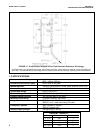
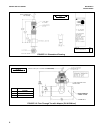
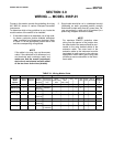
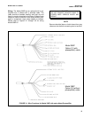
2.2.1 Flow Through and Insertion Mounting.
Model 396P and 396PVP Sensors have a 1-inch
MNPT process connection at the front of the sensor for
mounting into a 1-1/2 inch tee or the process pipes.
See Figure 2-1 through Figure 2-7 for installation con-
figurations.
NOTE
LARGE PIPE WRENCHES MUST NOT BE
USED TO TIGHTEN THE SENSOR INTO A
FLANGE OR OTHER TYPE OF MOUNTING.
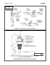
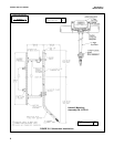
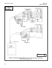
2.2.2 Submersion Mounting. Model 396P and
396PVP Sensors also have a 1 inch MNPT process
connection at the back of the sensor. Utilizing a stan-
dard 1 inch union, the sensor may be mounted to a 1
inch SCH 80 CPVC or PVDF standpipe (see Figure 2-
x). Tapered pipe threads in plastic tend to loosen after
installation. It is therefore recommended that Teflon
1
tape be used on the threads and that the tightness of
the connection be checked frequently to assure that no
loosening has occurred. To prevent rain water or con-
densation from running into the sensor, a weatherproof
junction box is recommended (see Figure 2-x). The
sensor cable must be run through a protective conduit
for isolation from electrical interference or physical
abuse from the process. The sensor should be installed
within 80° of vertical, with the electrode facing down.
The sensor’s cable should not be run with power or
control wiring.
1
Teflon is a registered trademark of E.I. du Pont de Nemours & Co.
2.1 UNPACKING AND INSPECTION.
Inspect the outside of the carton for any damage. If dam-
age is detected, contact the carrier immediately. Inspect
the hardware. Make sure all the items in the packing list
are present and in good condition. Notify the factory if any
part is missing. If the sensor appears to be in satisfactory
condition, proceed to Section 2.2, Mounting.
NOTE
Save the original packing cartons and materi-
als as most carriers require proof of damage
due to mishandling, etc. Also, if it is necessary
to return the sensor to the factory, you must
pack the sensor in the same manner as it was
received. Refer to Section 6.0 for return
instructions. If the sensor is to be stored, the
vinyl boot should be filled with pH buffer solu-
tion and replaced on sensor tip until ready to
use.
CAUTION
Buffer solution, in the vinyl boot, may cause
skin or eye irritation.
WARNING
Glass electrode must be wetted at all times (in
storage and in line) to maximize sensor life.
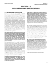
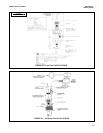
2.2 MOUNTING.
The sensor has been designed to be located in indus-
trial process environments. Temperature and pressure
limitations must not be exceeded at any time. A caution
label regarding this matter is attached to the sensor.
Please do not remove the label. See Figure 2-1.
CAUTION
Internal electrolyte fill solution may cause skin
or eye irritation.
Mounting Guidelines:
1. Shake the sensor in a downward motion to
remove any air bubbles that may be present inside
the tip of the pH glass.