


1. While obtaining a process solution sample (it is recommended that
the sample is taken close to the sensor), record the pH value that
is shown on the analyzer/transmitter display.
2. Measure and record the pH of the process solution sample with
another temperature compensated, calibrated pH instrument. For
best results, standardization should be performed at the process
temperature.
3. Adjust the analyzer/transmitter value to the standardized value.
5.2 MODEL 396P and 396PVP ORP SENSORS
5.2.1 SENSOR PREPARATION
. Most industrial applications have
a number of ORP reactions occurring in sequence or simultaneously.
There can be several components that are oxidized or reduced by
the reagents that are used. Theoretically, the ORP potential is
absolute because it is the result of the oxidation-reduction equilibri-
um. However, the actual measured potential is dependent on many
factors, including the condition of the surface of the ORP platinum
electrode. Therefore, the sensor should be allowed 1-2 hours to
become “conditioned” to the stream when first set-up or after
being cleaned.
5.2.2 ORP CALIBRATION
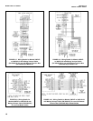
1. Make a temporary electrical connection between the sensor and
the instrument.
2. Obtain an ORP standard solution, or a standard solution can also be
made quite simply by adding a few crystals of quinhydrone to either
pH 4 or pH 7 buffer. Quinhydrone is only slightly soluble therefore a
few crystals will be required. (Refer to Section 4.3. for an alternate
ORP standard solution).
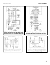
3. Immerse the sensor in the standard solution. Allow 1-2 minutes for
the ORP sensor to stabilize.
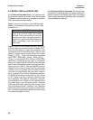
4. Adjust the standardize control of the instrument to the solution value
shown in Table 5-1 (below) or on the label of the standard solution.
The resulting potentials, measured with a clean platinum electrode
and saturated KCl/AgCl reference electrode, should be within ±20
millivolts of the value. Solution temperature must be noted to ensure
accurate interpretation of results. The ORP value of saturated quin-
hydrone solution is not stable over long periods of time. Therefore,
these standards should be made up fresh each time they are used.
5. Remove the sensor from the buffer, rinse and install in the process.
MODEL 396P and 396PVP SECTION 5.0
START UP AND CALIBRATION
SECTION 5.0
START UP AND CALIBRATION
5.1 MODELS 396P and 396PVP pH SENSORS
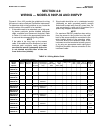
5.1.1 SENSOR PREPARATION. Shake down the sensor
to remove any air bubbles that may be present at the tip of
the pH glass bulb. In most cases, the pH sensor can simply
be installed as shipped and readings with an accuracy of ±
0.6 pH may be obtained. To obtain greater accuracy or to
verify proper operation, the sensor must be calibrated as a
loop with its compatible analyzer or transmitter.
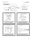
5.1.2 pH CALIBRATION. After a temporary connection is
established between the sensor and the instrument, a buffer
calibration may be performed. Consult appropriate pH/ORP
analyzer or transmitter instruction manual for specific calibra-
tion and standardization procedures, or see below for recom-
mended two-point buffer calibration procedure.
Recommended two-point buffer calibration procedure:
Select two stable buffer solutions, preferably pH 4.0 and 10.0
(pH buffers other than pH 4.0 and pH 10.0 can be used as long
as the pH values are at least two pH units apart).
NOTE
A pH 7.0 buffer solution reads a mV value of approxi-
mately zero, and pH buffers read approximately 59.1
mV for each pH unit above or below pH 7.0. Check the
pH buffer manufacturer specifications for millivolt values
at various temperatures since it may affect the actual
value of the buffer solution mV/pH value.
1. Immerse sensor in the first buffer solution. Allow sensor
to adjust to the buffer temperature (to avoid errors due to
temperature differences between the buffer solution and
sensor temperature) and wait for reading to stabilize.
Value of buffer can now be acknowledged by
analyzer/transmitter.
2. Once the first buffer has been acknowledged by the ana-
lyzer/transmitter, rinse the buffer solution off of the sensor
with distilled or deionized water.
3. Repeat steps 1 and 2 using the second buffer solution.
4. Once the analyzer/transmitter has acknowledged both
buffer solutions, a sensor slope (mV/pH) is established (the
slope value can be found within the analyzer/ transmitter).
5. The slope value should read about 59.1 mV/pH for a new
sensor and will decrease over time to approximately 47-
49 mV/pH. Once the slope reads below the 47-49 mV/pH
range, a new sensor should be installed to maintain accu-
rate readings.
Recommended pH Sensor S
tandardization:
For maximum accuracy, the sensor can be standardized online
or with a process grab sample after a buffer calibration has
been performed and the sensor has been conditioned to the
process. Standardization accounts for the sensor junction
potential and other interferences. Standardization will not
change the sensor’s slope but will simply adjust the analyzer’s
reading to match that of the known process pH.
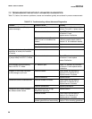
pH 4 Solution pH 7 Solution
Temp
°°
C 20 25 30 20 25 30
Millivolt Potential 268 264 260 94 87 80
TABLE 5-1. ORP of Saturated Quinhydrone
Solution (In Millivolts)
24