


8
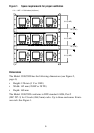
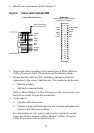
1. Identify the components shown in Figure 5.
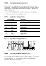
Figure 5. Sensor cable to Model 3500
2. Prepare the cable according to the instructions in Micro Motion’s
9-Wire Flowmeter Cable Preparation and Installation Guide.
3. Ensure that the cable has 360° shielding, continuous from the
transmitter to the sensor’s junction box. Two methods can be used:
• Metallic conduit
• Shielded or armored cable
Refer to Micro Motion’s 9-Wire Flowmeter Cable Preparation and
Installation Guide for specific instructions.
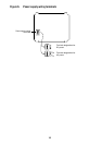
4. At the sensor:
a. Clip the cable drain wires.
b. Connect wiring inside the junction box housing and tighten the
screws to hold the wires in place.
For information on your sensor’s junction box terminals, see the
sensor installation manual or Micro Motion’s 9-Wire Flowmeter
Cable Preparation and Installation Guide.
9-wire cable from sensor
Model 3500
Keyed sensor wiring connector
(see Figure 3, page 6)
brown
red
green
white
blue
gray
orange
violet
yellow
black (drain wires
from all wire sets)
brown
yellow
violet
green
blue
red
black (drains)
orange
white
gray
c
c
c
c
c
c
c
c
c
c
c
c
c
c
c
c
2
4
6
8
10
12
14
16
18
20
22
24
26
28
30
32
a
a
a
a
a
a
a
a
a
a
a
a
a
a
a
a