


5
STEP 2. Installing guide rails and wiring connectors
Guide rails
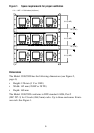
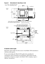
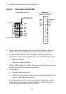
Positions of guide rails and wiring connectors are indicated in Figure 3,
page 6. Centers of guide rails should be 27 HP (27 TE) apart, for
example, at 1 HP (TE) and 28 HP (TE).
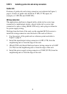
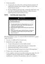
Wiring connectors
The applications platform is shipped with a solder-tail or screw-type
connector for input/output wiring, a keyed solder-tail or screw-type
connector for sensor wiring (Model 3500 only), and a plug-in connector
for power supply wiring.
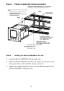
Working from the front of the rack, use the supplied M2.5x8 screws to
install the wiring connectors onto the back of the rack as follows:
1. Use the centers of the guide rails as reference points and refer to
Figure 3, page 6.
2. Install the input/output wiring connector at 4 HP (4 TE) from the
neighboring unit or from the edge of the rack.
3. (Model 3500 only) Install the keyed sensor wiring connector at 16 HP
(16 TE) from the neighboring unit or from the edge of the rack.
4. Install the power supply wiring connector at 25 HP (25 TE) from the
neighboring unit or from the edge of the rack.