


7
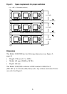
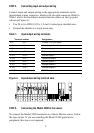
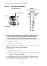
STEP 4. Connecting input and output wiring
Connect input and output wiring to the appropriate terminals on the
input/output wiring connector, which is the far right connector. Refer to
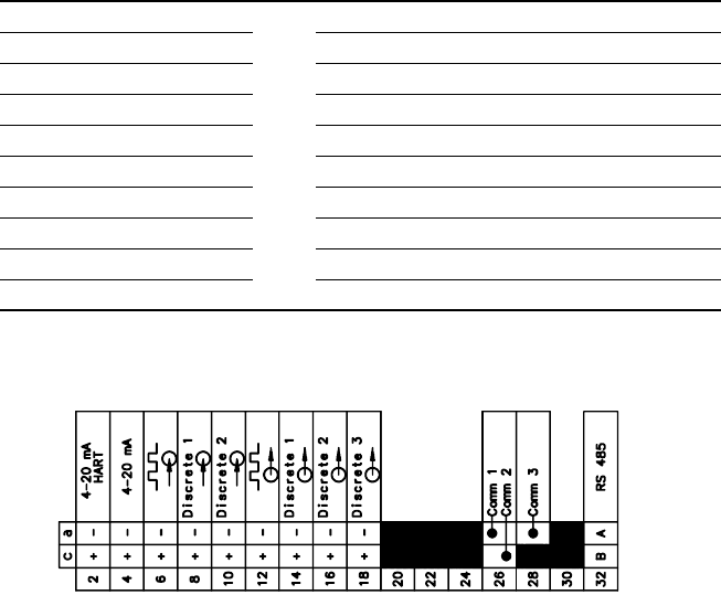
Table 1 and to the card that is inserted into the sleeve on the top panel
(shown in Figure 4).
• Use 24 to 16 AWG (0,25 to 1,5 mm
2
) twisted-pair shielded wire.
• Ground the shields at a single point only.
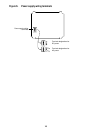
Figure 4. Input/output wiring terminal card
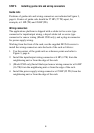
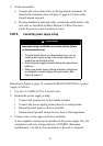
STEP 5. Connecting the Model 3500 to the sensor
To connect the Model 3500 transmitter to a Micro Motion sensor, follow
the steps below. If you are installing the Model 3300 applications
peripheral, this step is not required.
Table 1. Input/output wiring terminals
Terminal number Designation
c 2+ a 2 – Primary 4–20 mA output
c 4 + a 4 – Secondary 4–20 mA output
c 6 + a 6 – Frequency input
c 8 + a 8 – Discrete input 1
c 10 + a 10 – Discrete input 2
c 12 + a 12 – Frequency output
c 14 + a 14 – Discrete output 1
c 16 + a 16 – Discrete output 2
c 18 + a 18 – Discrete output 3
c 32 (B line) a 32 (A line) RS-485 output