December 2014
6
Quick Start Guide
Obstructions in the tank, or well, may generate echoes which can be confused with
the real liquid surface echo. Obstructions within the beam angle generate strong
false echoes. Wherever possible, the transmitter should be positioned to avoid
false echoes.
To avoid detecting unwanted objects in the tank or well, it is advisable to maintain
a distance of at least 1.3 in. from the center line of the transmitter for every foot
(11 cm per meter) range to the obstruction. (See Figure 5 on page 7).
No false echoes are generated if the transmitter is located near the side of the tank
or well and the wall is smooth and free of protrusions. However, there will still be a
reduction in the echo size. It is recommended that the transmitter be mounted no
closer than 12 in. (0,3 m) to the wall to avoid a large reduction in the echo size
If the transmitter is mounted in an enclosed tank with a domed top, avoid
mounting the transmitter in the center of the tank roof because this could act as a
parabolic reflector and create unwanted echoes
Avoid applications where heavy condensation could form on the transmitter face
If the transmitter is mounted in a stand-off or nozzle, the transmitter face should
protrude at least 0.2 in. (5 mm) into the tank
If the transmitter is used in environments where direct sunlight can cause high
surface temperatures on exposed instruments, a sun-shade is recommended
Mounting the transmitter above the liquid surface
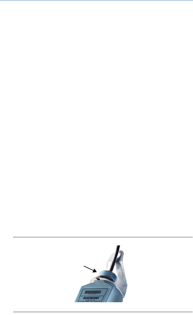
A 1 in. thread is provided to mount the transmitter (Figure 4). The thread form is either
BSPP (G1) or NPT, and is marked below the mounting thread.
Mounting bracket
The transmitter is supplied with a purpose made 316 Stainless Steel mounting bracket
(Figure 4) which should be used to mount the transmitter over the liquid surface.
The bracket is designed to fit over the threaded neck of the transmitter and is retained
by a locknut
Use a
chain or wire through the hole provided in the bracket, which is shaped to
ensure that the transmitter will hang perpendicular to the liquid surface.
Never suspend the transmitter by the cable. Check that the material of the chain or
wire is corrosion resistant to the liquids and any vapors present.
The bracket may be bolted to a suitable cross member above the liquid surface. Ensure
the transmitter is perpendicular to the surface to maximise the return echo size.
Figure 4. Mounting bracket
A. 1-in. mounting thread
A


