


1 Planning
Topics covered in this chapter:
• Installation checklist
• Best practices
• Temperature limits
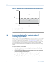
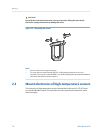
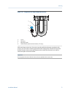
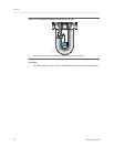
• Recommendations for hygienic and self-draining applications
1.1 Installation checklist
□
Make sure that the hazardous area specified on the approval tag is suitable for the
environment in which the meter will be installed.
□
Verify that the local ambient and process temperatures are within the limits of the
meter.
□
If your sensor has an integral transmitter, no wiring is required between the sensor
and transmitter. Follow the wiring instructions in the transmitter installation manual
for signal and power wiring.
□
If your transmitter has remote-mounted electronics, follow the instructions in this
manual for wiring between the sensor and the transmitter, and then follow the
instructions in the transmitter installation manual for power and signal wiring.
□
For the wiring between the sensor and the transmitter, consider maximum cable
lengths. The maximum distance between the sensor and transmitter depends on
the cable type. For all types of wiring, Micro Motion recommends using Micro
Motion cable.
Maximum lengths for Micro Motion cableTable 1-1:
Cable type To transmitter Maximum length
Micro Motion 9-wire 9739 MVD transmitter 1000 ft (300 m)
All other MVD transmitters 60 ft (20 m)
Micro Motion 4-wire All 4-wire MVD transmitters 1000 ft (300 m)
Maximum lengths for user-supplied 4-wire cableTable 1-2:
Wire function Wire size Maximum length
Power (VDC) 22 AWG (0,35 mm
2
) 300 ft (90 m)
20 AWG (0,5 mm
2
) 500 ft (150 m)
18 AWG (0,8 mm
2
) 1000 ft (300 m)
Signal (RS-485) 22 AWG (0,35 mm
2
) or larger 1000 ft (300 m)
Planning
Installation Manual 1