


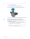
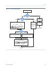
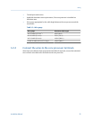
Core processor terminalsFigure 3-3:
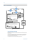
Connect the wires to the transmitter
terminals
(see the transmitter manual)
Reinstall and tighten the core processor cover
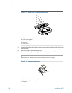
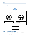
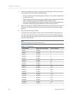
Core processor
type
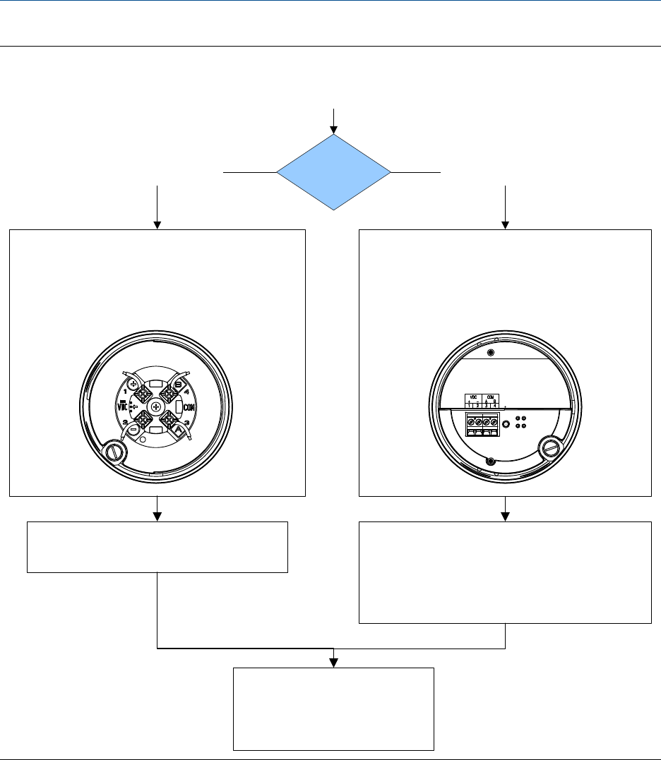
From Step 1 or 2
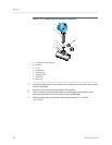
Connect the wires to the core processor terminals:
Red wire > Terminal 1 (Power supply +)
Black wire > Terminal 2 (Power supply –)
White wire > Terminal 3 (RS-485/A)
Green wire > Terminal 4 (RS-485/B)
Connect the wires to the core processor terminals:
Red wire > Terminal 1 (Power supply +)
Black wire > Terminal 2 (Power supply –)
White wire > Terminal 3 (RS-485/A)
Green wire > Terminal 4 (RS-485/B)
Enhanced
core processor
Standard
core processor
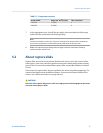
1. Reinstall the core processor cover.
2. Torque cover screws to:
• 10–13 in-lbs (1,13–1,47 N-m) for aluminum housing
• Minimum 19 in-lbs (2,1 N-m) for stainless steel
housing
3.3 Connect 9-wire cable
1. Prepare and install the cable according to the instructions in the Micro Motion 9-
Wire Flowmeter Cable Preparation and Installation Guide.
2. Insert the stripped ends of the individual wires into the terminal blocks. Ensure that
no bare wires remain exposed.
Wiring
26 Micro Motion ELITE