


9
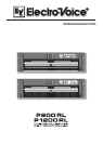
EASY REMOTE
Easy Remote provides a simple way to remotely power-on/off the power
amplifier. The Easy Remote function is only useful for appliances not
employing a RCM-24 Module. Controlling appliances with RCM-24 Module
installed per Easy Remote is practically pointless
.
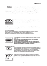
EASY REMOTE IN
Leaving the pins of the EASY REMOTE IN socket open, i.e. when connecting +5V, the appliance
power is switched on. When connecting the EASY REMOTE IN, i.e. when feeding 0V from the control
output, the appliance enters standby mode
.
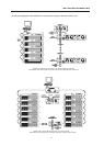
EASY REMOTE SLAVE
The EASY REMOTE SLAVE connector provides connection for additional appliances with Easy-
Remote function (e.g. for switching several devices within a rack-shelf ON/OFF).
The switching of the slave-units is delayed to prevent the mains fuses from blowing.
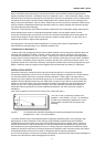
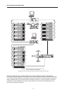
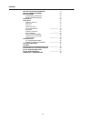
POWER AMPLIFIER OUTPUTS
4-pole binding-post terminals are provided for the power amplifier channels
„A“ and „B“.
When connecting loudspeaker systems, please mind the polarity
according to the here shown diagram.
Since the binding-post terminals might carry high voltages during
operation that might cause shock-hazard, closing the attached cover is
mandatory after establishing loudspeaker connections.
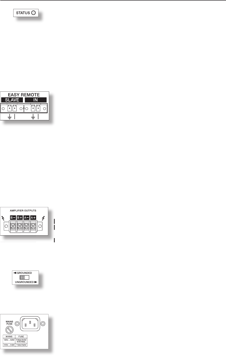
GROUND-LIFT SWITCH
The ground-lift switch allows eliminating noise loops. If the power amplifier is
operated together with other equipment in a 19“ rack-shelf, setting the switch
to its GROUNDED position is recommended. If the power amplifier is
operated together with appliances with differing ground potentials, setting
the switch to its UNGROUNDED position is recommended
.
MAINS INPUT
Under normal circumstances, the mains fuse only blows in case of fault.
Replacing the fuse is only permissible when using a new fuse of the same
type with identical amperage, voltage and blow characteristics. If the mains
fuse blows more often, please contact an authorized service centre.
When connecting loudspeaker systems, please mind the polarity
according to the here shown diagram.
operation that might cause shock-hazard, closing the attached cover is
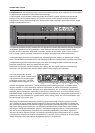
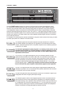
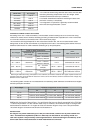
REAR VIEW
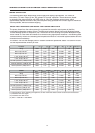
The STATUS LED provides optical indication of CAN-bus traffic. When the
power amplifier’s address is set to “00” so that it is separated from the CAN-
bus, the STATUS LED blinks every 3 seconds. When the power amplifier’s
address is set between “01” and “250” and no CAN-bus activity has taken
place yet, the LED blinks every second. As soon as CAN-bus communication is recognized, the LED is
activated for at least 100ms whenever the power amplifier actively sends data on the CAN-bus.
The STATUS LED may also be activated from the PC. In this case, the LED of the according power
amplifier blinks fast and steady while all other status-LEDs within the system stay dimmed
.