


14
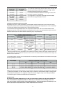
MAINS OPERATION & RESULTING TEMPERATURE
P1200RL
U
Mains
[V]
I
Mains
[A]
P
Mains
[W]
P
out
[W]
P
d
[W]
BTU/hr
(3)
Idling
230V
0.55
85
-
85
290
Max. Output @ 8
Ω
(1)
230V
6.40
1185
2 x 380
425
1450
Max. Output @ 4
Ω
(1)
230V
10.5
2030
2 x 600
830
2832
max. Output @ 4
Ω
(1)
230V
6.60
1230
2 x 200
830
2832
max. Output @ 4
Ω
(2)
230V
3.80
675
2 x 75
525
1791
Normal Operation (-10dB) @ 4
Ω
(1)
230V
3.78
670
2 x 50
570
1945
Nominal operation (0dB)
@ 4
Ω
(1)
230V
9.69
1870
2 x 500
870
2969
Alarm Operation (-3dB)
@ 4
Ω
(1)
230V
7.27
1370
2 x 250
870
2969
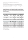
P900RL
U
Mains
[V]
I
Mains
[A]
P
Mains
[W]
P
out
[W]
P
d
[W]
BTU/hr
(3)
Idling
230V
0.45
70
-
70
239
Max. Output @ 8
Ω
(1)
230V
4.97
920
2 x 280
360
1228
Max. Output @ 4
Ω
(1)
230V
8.16
1580
2 x 450
680
2320
max. Output @ 4
Ω
(1)
230V
5.13
960
2 x 150
660
2252
max. Output @ 4
Ω
(2)
230V
2.90
520
2 x 56.3
407.5
1390
Normal Operation (-10dB) @ 4
Ω
(1)
230V
2.84
505
2 x 35
435
1484
Nenn Operation (0dB)
@ 4
Ω
(1)
230V
7.32
1410
2 x 350
710
2423
Alarm Operation (-3dB)
@ 4
Ω
(1)
230V
5.48
1030
2 x 175
680
2320
For approximation; when operating the appliance at 120V mains the stated current values need to be doubled.
(1) modulated with sine signal
(2) modulated with VDE-noise
(3) 1BTU = 1055.06J = 1055.06Ws
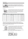
MAINS OPERATION
The following tables allow determining power supply and cabling requirements. The values of
the column „1/8 max. Output @ 4
Ω
” are relevant for “normal” operation. These values are based
on operating the power amplifier with VDE-noise at 1/8 of the maximum output power, which
approximately equates the load of the power amplifier being operated with a music signal at maximum
volume possible, without noticeable clipping
.
RESULTING TEMPERATURE INSIDE THE POWER AMPLIFIER
The power drawn from the mains network is converted into acoustic output power to feed the
connected loudspeaker systems & heat. The difference between drawn power and dispensed power
is called leakage power or dissipation (Pd). The amount of heat resulting from power dissipation might
remain inside of a rack-shelf and needs to be diverted using appropriate measures. The following table
provides auxiliary means for calculating the temperatures inside of a rack-shelf system/cabinet and the
ventilation efforts necessary.
The column “Pd” lists the leakage power in relation to different operational states. The column “BTU/hr”
lists the dispensed heat amount per hour
.