


Please note: the pull-up location on the lower
section of the back panel of the enclosure MUST
be used to hang the system in order to provide a
safe, stable mounting system. The pull-up point pro-
vides an additive safety, as it is capable of holding
the speaker system with a safety factor of at least
5:1 in the unlikely event of a failure in the main load-
bearing system.
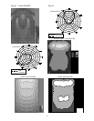
For the EVI-28, the mounting holes are posi-
tioned very near the center of gravity for easy aim-
ing. The U-brackets may be rotated all the way
around the back of the enclosure, allowing easy in-
stallation and aiming. The maximum vertical angle
that may be reached is approximately 35°, less if
the loudspeaker is mounted flush against a ceiling.
In this case, the enclosure may be rotated upwards
by at least 15°, more than sufficient for nearly any
application (see Figure 15). The brackets are sup-
plied with friction washers that will prevent the en-
closure from rotating over time, but to be abso-
lutely certain, the installer should use a set screw in
the threaded hole to fix the enclosure permanently
in position.
The described hanging methods are rated for
suspending only one speaker (with a minimum of
an 8:1 safety factor). Hanging any additional
weight from the speaker will exceed its strength
rating and create an unsafe condition.
A Sampling of EVI Applications:
Now that the technical details are covered,
here are a few ideas on applications that the EVI
systems will cover with far more uniform sound and
lower overall cost than any conventional enclosure.
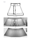
The first and most obvious application is in a church
or some other well-defined space that has a fairly
tall ceiling, and proportions of roughly 2 x 3 (see
Figure 1). In this application, the EVI systems can
easily replace a central cluster or distributed sys-
tem with a single low-cost enclosure and still main-
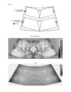
tain a more uniform sound distribution. Figure 2
shows a similar room, but with a somewhat longer
throw, where the EVI systems also perform very
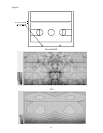
well. Many auditoriums and theatres are much wider
than a typical set of church pews, so Figure 6 shows
a fairly standard auditorium floor plan and possible
mounting locations. Any interference between the
systems will be concentrated in the center aisle,
where sound quality is not as critical. The EVI-12,
EVI-15 and EVI-28 systems are also ideal for re-
placing distributed arrays, providing much more
uniform coverage at a lower cost. See Figure 7 for
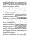
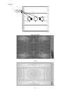
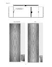
is that 3dB of long-throw SPL and 1.5-2dB of side-
fill level has been lost. A higher resolution data file
is needed to provide a “real world realistic” simula-
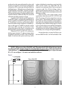
tion. Figure 5 shows the raw 2° polar data with
the averaged 10° data superimposed. Also shown
are floorplans from our 2° modeler, DCSO, the 5-
degree AcoustaCADD and 10-degree EASE. By
comparing the 2°, 5° and 10° resolution you can eas-
ily see the apparent loss in direct-field SPL. This
loss shows up as a series of “steps” along the length
of the room and an artificially narrowed throw with
less SPL in the corners than would be achieved in a
real-world installation. Please keep this in mind
when using simulation software.
Hanging EVI Systems:
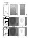
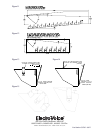
For the EVI-12 and EVI-15 the physical
mounting of the systems have been designed to be
as easy as possible, with two simple options avail-
able. By far, the easiest solution is to use the op-
tional sturdy, cost effective EVI-12MB or
EVI-15MB U-Brackets that mount to the 3/8-16
T-nut locations on the sides of the enclosure. The sup-
plied forged-shoulder eyebolt must be used in the t-nut
location on the lower back side of the system as a
pull-up point (see figure 13). With this arrangement,
the U-Bracket holds approximately 80% of the
weight of the system, and the pull-up point pro-
vides a convenient method of adjusting the aiming
angle. The U-Brackets have easy-to-install bolt
patterns and include three sets of OmniMount 100
bolt patterns. For most applications, this will be
the preferred methodology as it is fast, aesthetically
pleasing, flexible and inexpensive. However, this
method will not work in all applications, so we have
included a second set of T-nut locations on the top
of the enclosure so that the hanging cables can be
completely out of view from below (see Figure 14).
The front pair of hanging points should carry ap-
proximately 50 lbs of the enclosure’s weight, with
the required pull-up point taking the balance of
the weight (about 5 lb). The T-nut locations are
intended to be used only with forged shoulder
eyebolts with a minimum tensile strength of 350 kg
(770 lb). The inexpensive EBK-1 kit includes three
eyebolts, especially helpful when access to quality
forged shoulder eyebolts is limited. Please keep in
mind that the center of gravity is designed to be
behind the main hanging points. This means that
the back of the system will rotate as much as 50
degrees down, allowing easy aiming adjustment to
virtually any angle.
5