


4
is mounted above a flat floor is with the top of the
enclosure parallel to the floor. In this orientation,
the system will provide even SPL over a floorplan
that is approximately twice as wide as the mounting
height, and five times as long. Tilting the enclosure
down by approximately 10- to 15° relative to the
slope of the floor will produce a floorplan the same
as an EVI-12 or EVI-15. At the standard aiming,
the 45° nearfield operational angle defines an ap-
proximate offset to the first useable row of one-half
the height of the speaker system above the listening
plane.
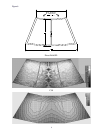
In a typical installation, the top surface of the loud-
speaker will point slightly above the head height of
the furthest targeted seating or standing area. This
will ensure the minimum amount of slap echo from
the back wall. In an under-balcony situation, the
sharp cutoff above the zero degree axis prevents
early ceiling reflections from causing interference
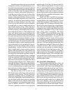
patterns in the listening area. Since an EVI-28 has
a very smooth and rapid drop-off towards directly
below the cabinet, you can actually stand right in
front of the speaker (see Figure 12) without ear
strain or heavy microphone feedback. The remark-
able absence of lobes to the rear allows the system
to be mounted directly overhead to target a par-
ticular area without disturbing the audience below
or behind the cabinet.
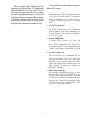
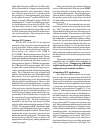
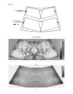
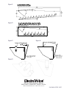
For example, FIGURE 11 shows a typical under-
balcony application that has a floor with an upward
slope of 5°. The speaker is mounted 10 feet above
the seated head height, so the horizontal width is
fixed at approximately 20 feet. The enclosure is
tilted back by 5° to provide a 50-foot throw, with
the outskirts of the pattern filling in the rear aisle
area with tonally accurate but reduced overall SPL.
If the under-balcony seating area is only 35 feet
deep, then the enclosure should be tilted down by
about 10° relative to the floor in order to prevent
excess slap echo and preserve intelligibility.
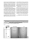
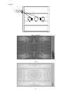
Figure 12 shows a typical small-room application,
perfect for a 20-foot by 30-foot boardroom or
meeting hall. In this case, the head height is actually
defined by a standing height of approximately 6 feet,
so the long-throw axis should be very close to hori-
zontal. Then the included 40 degree angle points
directly towards the entire listening area, minimizing
slap echo while retaining a full width, high intelligi-
bility and even SPL throughout the listening area.
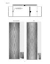
Q vs. Intelligibility:
The “Q” of a system is a good measure of the
system’s directivity, and in some ways a good mea-
sure of whether the system’s in-room response will
be consistent across the frequency range. A typi-
cal 12-inch two-way system with a 60
o
x 40
o
horn
will maintain a fairly constant Q from 16-30 or
12-15 dB (normally about 26, or 14dB) from
3,000–20,000 Hz, and a 90
o
x 40
o
a Q of 13-15
(11-12dB). Very-high-directivity horns such as a
40
o
x 20
o
will have an average Q in the range of
45 (16.5 dB), and very-low-directivity horns like a
120
o
x 40
o
will have a Q of 7-9 (8.5-9.5 dB). It is
generally thought that a high-directivity horn will
have greater intelligibility across a given pattern area
than a lower-Q device, and this is true in most cases.
Also true in most cases is that a standard horn pat-
tern will not fill a typical floorplan, thus drastically
reducing the effectiveness of the higher Q. In direct
comparison, the VI horn pattern will fill a majority
of floorplans with direct-field sound rather than re-
lying on reverberant energy to “fill in the gaps” in
overall sound quality and quantity. The Q of the VI
systems are very consistent from 1,000–20,000 Hz,
with a range of 10-18 (10-12.5 dB) and an aver-
age Q of 13.5 (11.5dB) or consistent with the overall
directivity of a 90
o
x 40
o
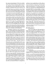
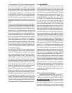
system. This might lead
you to believe that the VI systems are “low-Q” and
inappropriate for highly reverberant rooms, but the
plots of the direct-field SPL and its accompanying
C50 ratio show a significant advantage to the VI
system over a conventional 60
o
x 40
o
system. As we
all know, high Q only helps when the polar response
fits into the listening space as closely as possible.
Please keep this in mind when using Q as a bench-
mark for system intelligibility. For those unfamiliar
with the term C50, it is a measure of intelligibility
defined by the acoustic power in the room in the
first 50 msec divided by the power from 50 msec
to infinity, expressed in dB. The minimum recom-
mended level of intelligibility is 0 dB, roughly equiva-
lent to 10% Alcons.
A Note on Simulation Software:
Data files for AcoustaCADD
TM
and EASE
TM
are available from Electro-Voice’s BBS, by special
request or on Electro-Voice’s Website (http://
www.electrovoice.com). The figures have all been
produced in EASE, but with the current 10° resolu-
tion of the software, much of the 2° resolution data
we collect has been lost in the required averaging
translation to the 10-degree format. The net result