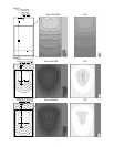
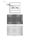
the same mounting height of 18 feet, but with the
front of the enclosure tilted up by approximately
10° (see Figure 2), the total floorplan now encom-
passed the same 36 foot width, but at least 64 feet
in length, an additional 10+ feet of extension. Of
course, the front row position has moved back
about 5 feet with the change in angle as shown, but
this is easy to account for when initially positioning
the system (and is exactly what happens if you take
a conventional system and change the angle). For
rooms that are closer to square, tilting the loud-
speaker system down by 15° provides a very clean
square pattern. In this case, the offset to the first
row is about 0.25 times the height of the system.
For example, a tall, square room is about 60 feet
wide, and only 65 feet long. Tilting the enclosure
down by 15° at a 30 foot mounting height makes a
60 foot wide by 60 foot long pattern. The offset to
the first row is 0.25 multiplied by the 30 foot height,
or about 7.5 feet forward from the back of the en-
closure. Minor adjustments in aiming will make the
SPL fill the room very evenly with no loss in tonality
in the corners and high overall intelligibility.
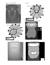
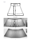
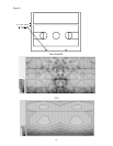
By contrast, a typical two-way system with a
60° x 40° CD horn in the same mounting location as
Figures 1 and 2 (see Figure 3) produced a floor plan
that sounded tonally fairly consistent with a 20- to
24-foot width and 30-foot depth with an offset of
nine feet to the front row.
On paper, this seems like
adequate performance, but in the room it has very
noticeable
(6 dB or greater) variation in overall level
from side to center, and in some aiming cases over
10 dB of variation from front to back as well as a
pronounced lemon shape. The sides of the first
three to five rows in a church and the last few rows
were noticeably muted and much lower in overall
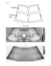
level. As mentioned before, a two-horn system can
work fairly well, but the physical offsets required
for installation inevitably result in some amount of
destructive interference throughout the room
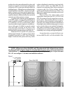
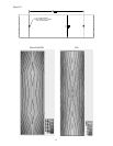
(see Figure 4). Figure 4 was produced using a
90° x 40° CD horn aimed down by 65° and a
60° x 40° horn aimed down by 30°. The actual
physical offsets were used to simulate the floor
response in direct-field SPL. The displayed figure
agrees very well with the measured response, show-
ing a 14-dB variation at 4kHz in a distance of 3 feet
horizontally. Tonal changes as a result of interfer-
ence pattern change versus frequency were clearly
audible in an acoustically well-behaved room, but
were overall much less audible than for a single sys-
tem with a conventional CD horn. Locating drivers
and horns closer together than possible with me-
dium-format horns will produce somewhat better
results, but will always result in fairly severe lobing.
Polar measurements in 2° increments show the
lobing very well, but the smoothing required for trans-
lation to the EASE 10° resolution database will elimi-
nate the vast majority of peaks and dips, resulting
in what appears to be a fairly smooth simulation. In
contrast, the new VI systems have no problems with
interference, and maintain very good tonality even
far to the sides and to the back, outside the “equal-
SPL” pattern area. This effect is due to the precise
matching of directivities in the midrange and treble,
giving a consistent (although noticeably quieter) fre-
quency response out to nearly 50 feet in width and
65–70 feet in length from the same 18-foot height
and 0° aiming angle. This has the advantage of pro-
viding a much more uniform power response into
the reverberant field, ensuring that the inevitable
reflections (minimized by the VI concept) are con-
sistent in tonal quality.
EVI-28 Installation:
The EVI-28 makes use of the same high-fre-
quency horn as the EVI-12 and EVI-15, but in-
cludes a pair of high-power, high-efficiency 8” woof-
ers in a very compact package. The system is pro-
vided with a 2,000-Hz passive crossover featuring
tweeter protection and a proprietary passive equal-
ization circuit that provides frequency-shading, am-
plitude-shading and time delay to the two woofers.
An Acoustic Lens Filter on the grille helps to elimi-
nate spurious lobes and provides a degree of acous-
tic loading. These features heavily modify the polar
response of the two woofers, providing an extremely
uniform polar pattern with a shape that matches the
VI horn’s unique SPL profile. They also smooth
the transition between woofers and the horn to mini-
mize horizontal lobes, providing amazingly even
coverage through the crossover point. This extends
the VI characteristic down to 500 Hz in an extremely
compact enclosure.
The high-frequency horn in the EVI-28 is
mounted tilted 15° back relative to the EVI-12
and EVI-15. Along with the polar steering in the
woofer’s crossover, this arranges the dispersion for
long throws relative to the mounting height. The
recommended operational vertical angle is minus
5°from the top surface of the enclosure to minus
45°, defining a maximum used vertical dispersion
of 40°. The standard aiming of the system when it
3


