


PAGE 23
SPECIFICATIONS ARE SUBJECT TO CHANGE WITHOUT NOTICEDMS3040/3080/3120
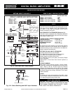
INSTALLATION AND WIRING
MODULE CONNECTOR DIAGRAM
Connector
Top
Gold
Contact
Front
View
Side
View
Cable from
Amplifier
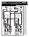
3120 Module Schem
6
5
4
3
2
3
6
5
4
3
2
1
6
5
4
3
2
1
TO
MODULE
PCB
CONNECTOR
CN201
1
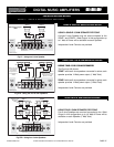
MODULE CONNECTOR
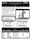
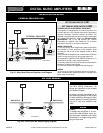
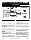
Connector Contacts
6 = + 24V DC
5 = Module Input
4 = Module Output
3 = Ground
2 = Mute Buss 1
1 = Mute Buss 2
Fig. 23 - Module Connector Contacts Diagram
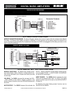
MODULE CONNECTOR DIAGRAM - The above Diagram indicates the function of each of the six contacts of the Module
Connector. The Module Blue Ribbon Connector is attached to a wire harness and left floating beyond the Module Port
Cover. The Wire Harness Amplifier End is attached to Connector No. CN201 and plugged into the mating connector on the
Main Printed Circuit Board.
MODULE DEFAULT SETTINGS
Connector
Top
Gold
Contact
Front
View
Side
View
Cable from
Amplifier
3120 Module Functions
6
5
4
3
2
3
6
5
4
3
2
1
6
5
4
3
2
1
TO
MODULE
PCB
CONNECTOR
CN201
1
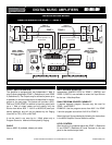
MODULE CONNECTOR
Connector Contacts
6 = + 24V DC
5 = Module Input
4 = Module Output
3 = Ground
2 = Mute Buss 1
1 = Mute Buss 2
V1
V2
OFF
VOX 2 BUSS OFF
X
VOX SEND
SW221
VOX 1 BUSS OFF
X
JUMPER
M2
M1
OFF
MUTE 2 BUSS OFF
X
X
MUTE 1 BUSS OFF
MUTE RECEIVE
JUMPER
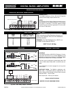
MODULE VOX - MUTE
JUMPERS AND INPUT SOURCE
SWITCH DEFAULT SETTING
SW222
MODULE INPUT
AUX 2 SOURCE
AUX 1 SOURCE
SW209
AUX 1 AUX 2
AUX 1 - AUX 2 SWITCH
MODULE OUTPUT
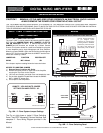
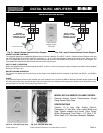
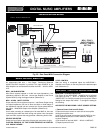
Fig. 23A - Module VOX - MUTE - INPUT SOURCE Default Settings
MODULE FUNCTIONS - The Module Port accepts a stan-
dard audio Module. When a Module is utilized several func-
tions can be activated by the Jumpers and Switch provided
for this Input.
VOX SEND - The SW221 Jumpers Set activates the VOX 1
- VOX 2 SEND or both. When a Signal is present at the
Module Output (Contact 4) then the VOX BUSS selected will
be active.
MUTE RECEIVE - The SW222 Jumpers Set activates the
MUTE 1 - MUTE 2 RECEIVE or both. When a Signal is pres-
ent at the MUTE BUSS 1 or MUTE BUSS 2 the MODULE
will be MUTED accordingly.
INPUT SOURCE - The SW209 Switch selectes the Input
Source for the Module either AUX 1 or AUX 2. The Signal
present at either Input will be sent to the MODULE INPUT
(Contact 5).
By selecting the proper Setting several functions can be
derived from the Module.
PROFESSIONAL AUDIO & SOUND
®
TM
DIGITAL MUSIC SERIES
DIGITAL MUSIC AMPLIFIERS