


PAGE 10
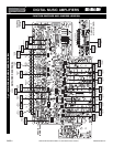
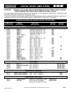
SPECIFICATIONS ARE SUBJECT TO CHANGE WITHOUT NOTICE DMS3040/3080/3120
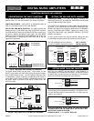
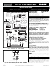
INPUT 1 SETTING AS A MICROPHONE INPUT
MICROPHONE TYPE
The Microphone Input accepts Low Impedance (250-600 ohm)
Dynamic Microphones.The Microphone may be a balanced output
type (three wire) or an unbalanced output type (two wire).
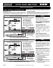
PASO MICROPHONES
All PASO low impedance Microphones have a balanced output for
best performance. Connect the RED lead to terminal HOT, the
WHITE lead to terminal COM and the SHIELD to terminal G.
3120 Micbal 01
THREE LEADS BALANCED MICROPHONE WIRING
SHIELD
MIC
Lo Z
RED
WHITE
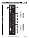
INPUT 1 - Default Jumper Settings
INPUT 3 (MIC)
INPUT 2 (MIC)
INPUT 1 (MIC)
G COM HOT G COM HOT G COM HOT
BALANCED
250ohm 1.5mV
The Diagram at Left shows the
Default Settings for INPUT 1.
VOX 1 is SWITCHED ON
VOX 2 is SWITCHED OFF
MUTE 1 is SWITCHED OFF
MUTE 2 is SWITCHED OFF
When the INPUT 1 (MIC 1) is
activated the VOX 1 BUSS is ON
and it will MUTE any Input with the
MUTE 1 Setting SWITCHED ON.
NOTE: To change the
INPUT Default Settings
refer to the appropriate
section in this Manual
The microphone leads color refers to Paso Microphones only.
When using other brand refer to instructions packed with that
unit.
V1
V2
OFF
VOX 1 BUSS
ACTIVATED
VOX 2 BUSS OFF
M2
M1
OFF
INPUT 1
X
MUTE 2 BUSS OFF
X
X
MUTE 1 BUSS OFF
AUDIO OUT
MIC IN
Input 1 - V1 - 01
VOX SEND
MUTE RECEIVE
SW215
SW220
JUMPER
JUMPER
VOX - MUTE JUMPERS SETTING
=
JUMPER
JUMPER
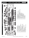
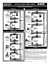
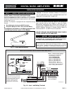
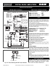
TWO LEADS UNBALANCED MICROPHONE WIRING
INPUT 1 - Default Jumper Settings
INPUT 3 (MIC)
INPUT 2 (MIC)
INPUT 1 (MIC)
G COM HOT G COM HOT G COM HOT
BALANCED
250ohm 1.5mV
The Diagram at Left shows the
Default Settings for INPUT 1.
VOX 1 is SWITCHED ON
VOX 2 is SWITCHED OFF
MUTE 1 is SWITCHED OFF
MUTE 2 is SWITCHED OFF
When the INPUT 1 (MIC 1) is
activated the VOX 1 BUSS is ON
and it will MUTE any Input with the
MUTE 1 Setting SWITCHED ON.
NOTE: To change the
INPUT Default Settings
refer to the appropriate
section in this Manual
SHIELD
MIC
Lo Z
HOT LEAD
3120 Micunbal 01
V1
V2
OFF
VOX 1 BUSS
ACTIVATED
VOX 2 BUSS OFF
M2
M1
OFF
INPUT 1
X
MUTE 2 BUSS OFF
X
X
MUTE 1 BUSS OFF
AUDIO OUT
MIC IN
Input 1 - V1 - 01
VOX SEND
MUTE RECEIVE
SW215
SW220
=
JUMPER
JUMPER
JUMPER
JUMPER
VOX - MUTE JUMPERS SETTING
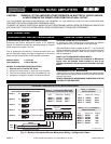
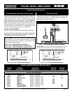
WIRING
CABLE
MICROPHONE INPUT
Attach the microphone leads to the ter-
minal strip as per diagrams at left.
DO NOT GROUND THE MICROPHONE
CABLE SHIELD TO THE CHASSIS OF
THE AMPLIFIER
BALANCED MICROPHONE
IMPORTANT NOTE: The use of an
unbalanced Microphone (two leads) is
not recommended. For best results in a
PA Application always use a
Unidirectional Dynamic, Low
Impedance, Balanced Microphone
(three leads).
UNBALANCED MICROPHONE
Attach the Microphone leads to the ter-
minal strip as per diagram in Fig 8A. The
cable length should not exceed: 15 Ft.
(4.5 m).
Fig. 10 - Balanced Microphone Input 1 Wiring
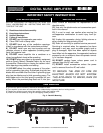
CAUTION:
TO PREVENT POSSIBLE DAMAGE TO SPEAKERS OR THE AMPLIFIER
ALL INPUT CONNECTIONS MUST BE MADE WITH THE AMPLIFIER POWER OFF.
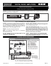
CABLE LENGTH - If the distance
between the Microphone and the
Amplifier Input is greater than 15 ft (4.5
m) a Balanced Microphone must be
used. Use a two conductor shielded wire
and connect Microphone to Amplifier as
per Diagram in Fig. 10.
MICROPHONE CABLE ROUTING - The
Microphone Cable should be carefully
routed. Improper Cable routing will
cause spurious oscillations, regenerative
noises, hum, etc. that may permanently
damage the Amplifier.
z Do not route cable next to power
lines.
z
Do not route cable near or over
Fluorescent Fixtures.
z
Do not route cable next to
Speaker Wires.
z
Do not install cable inside Power
Line Conduits.
z
Avoid the use of staples that may
penetrate the cable.
Fig. 10A - Unbalanced Microphone Input 1 Wiring
INSTALLATION AND WIRING
PROFESSIONAL AUDIO & SOUND
®
TM
DIGITAL MUSIC SERIES
DIGITAL MUSIC AMPLIFIERS