


PAGE 12
SPECIFICATIONS ARE SUBJECT TO CHANGE WITHOUT NOTICE DMS3040/3080/3120
INPUT CONNECTIONS
CONFIGURATION TABLES
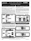
CONDENSER AND ELECTRET TYPE MICROPHONES
Condenser and Electret Microphones require a DC Operating
Voltage. The Amplifier provides this operating voltage or Phantom
Power selectively on Inputs.1-2-3-4-5.
Prior to selecting the Condenser or Electret Microphone be sure
that the Operating Voltage and Output Impedance of the device
match the Input characteristics of the Amplifier listed below.
Phantom Power = 18 Volt DC
Input Impedance = 250 to 600 ohm
ACCESS TO PHANTOM POWER SELECTORS
1) Remove Power Cord from AC Outlet.
2) Remove the three screws on each side of the Amplifier.
3) Lift Cover and carefully slide Cover out towards the rear.
4) Jumpers are located on the Main Printed Circuit Board.
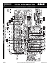
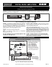
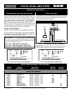
Fig. 12 - Balanced Condenser/Electret Microphone Wiring - Configuration Tables
THE FOLLOWING INSTRUCTIONS REQUIRE THE REMOVAL OF THE AMPLIFIER PROTECTIVE COVER AND ARE
PROVIDED FOR USE BY QUALIFIED PERSONNEL ONLY.
TO AVOID THE RISK OF ELECTRICAL SHOCK DO NOT PERFORM ANY INSTALLATION OR SERVICING UNLESS YOU
ARE QUALIFIED TO DO SO. REFER INSTALLATION OR SERVICING TO QUALIFIED PERSONNEL.
CAUTION ! REMOVAL OF THE AMPLIFIER COVER PRESENTS AN ELECTRICAL SHOCK HAZARD
ALWAYS REMOVE THE POWER CORD FROM THE AC WALL OUTLET
3120 Micbal Electret
BALANCED CONDENSER/ELECTRET MICROPHONE WIRING
SHIELD
MIC
Lo Z
INPUT 3 (MIC)
INPUT 2 (MIC)
INPUT 1 (MIC)
G COM HOT G COM HOT G COM HOT
BALANCED
250ohm 1.5mV
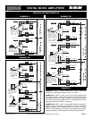
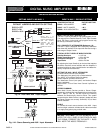
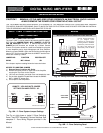
MIC INPUTS PHANTOM POWER JUMPER SETTING
WHEN USING ELECTRET MICROPHONES
-0 +18V +18V
INPUT 1- 2 - 3 - 4 - 5 DEFAULT
JUMPER SETTINGS
Input Jumper No. Setting
INPUT 1 SW201 OFF
INPUT 2 SW202 OFF
INPUT 3 SW203 OFF
INPUT 4 SW204 OFF
INPUT 5 SW207 OFF
SW201
OFF
JUMPER
On
SW202
OFF
JUMPER
On
SW203
OFF
JUMPER
On
SW204
OFF
JUMPER
On
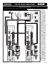
INPUT 1
INPUT 2
INPUT 3
INPUT 4
(When set as MIC 4)
HOT LEAD
HOT LEAD
SW207
OFF
JUMPER
On
INPUT 5
(When set as MIC 5)
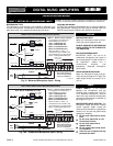
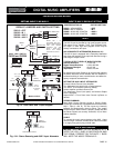
Input Switch No. Setting
INPUT 4 SW228 AUX 1
INPUT 5 SW208 AUX 2
INPUT 5 SW229 AUX 2
INPUT 4 - 5 DEFAULT
SWITCH SETTINGS
Input Switch No. Setting
INPUT 4 SW228 MIC 4
INPUT 5 SW208 MIC 5
INPUT 5 SW229 MIC 5
INPUT 4 - 5 SWITCH SETTINGS WHEN
CONFIGURING AS MICROPHONE INPUT
CONDENSER AND ELECTRET MICROPHONES
WIRING
PHANTOM POWER SELECTOR JUMPER
By following the Main Printed Board Layout locate the Selector
Jumpers with the ID No. as indicated on the Table below.
Reset the Phantom Power Jumpers for INPUT 1 - 2 or 3 to the ON
position as desired. Lift the Mini Jumper out of the socket pins and
re-position to the ON position. Make sure the Jumper is lined up
with the socket pins.
INPUT 4 and 5 CONFIGURED AS MIC INPUTS
If INPUT 4 and INPUT5 need to be configured as Microphone
Inputs, reset the Phantom Power Jumpers as well as the
Switches provided for the two Inputs as indicated in the Table
below.
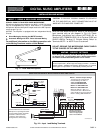
PHANTOM POWER SELECTORS
CONDENSER/ELECTRET MICROPHONE
Carefully follow the wiring instruction packed with the Microphone
used. Attach the microphone leads to the terminal strip as per dia-
gram per Fig. below.
DO NOT GROUND THE MICROPHONE CABLE SHIELD TO THE
CHASSIS OF THE AMPLIFIER
PROFESSIONAL AUDIO & SOUND
®
TM
DIGITAL MUSIC SERIES
DIGITAL MUSIC AMPLIFIERS