


Checking the ground fault surveillance function:
When the NRS 90224 is installed and the power amplifier is switched on, the green READY indicator (7) has to
light. Utilizing an external switch to connect one pole of the 100V-loudspeaker network via a 47 k ohms resistor for
approximately 5 seconds to ground potential, the corresponding red GROUND FAULT indicator (6) has to light and
the READY fault message relay of the INPUT MODULE NRS 90225 drops while the green READY indicator (7)
stays lit. After releasing the button, the indication and the fault message are maintained. The TEST button (3) has
to be used to reset the ground fault surveillance function. For further details on checking the function with the
REMOTE MODULE NRS 90222 being included in your installation, please refer to the PROMATRIX handbook.
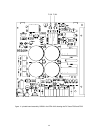
9. 19"-case and 19“-rack-shelf system installation
Note Operation of the power amplifiers DPA 4120 and DPA 4140 with enclosure cover plates detached is
strictly prohibited.
When mounting the power amplifiers within rack-cases or rack-shelf systems make sure to provide sufficient
airflow. The space between the rear panel of the amplifier and the inner wall of the rack-case has to be at least 60
mm x 330 mm. A free space of at least 100 mm above the rack-shelf system is needed to provide sufficient air
circulation. Since it is possible that during operation the temperature inside the rack system increases by 10° C, the
maximum allowable ambient temperatures of the rest of the incorporated modules and appliances within a specific
rack-shelf or rack-case have to be taken into careful consideration.
Note To ensure trouble-free operation of the appliance, the maximum permissible ambient temperature of
+40°C is not to be exceeded.
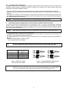
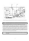
10. Ground lift switch CIRCUIT A TO CHASSIS SWITCH
The ground lift switch CIRCUIT A TO CHASSIS SWITCH (19) provides the possibility to separate the signal ground
from the enclosure (ground potential). This is mainly meant to eliminate noise-problems which are introduced
through ground-loops, without jeopardizing the security. In case several appliances within a single rack-case or
rack-shelf are furnished with ground lift switches, it is recommended to set all devices but one to "ungrounded“. Set
one appliance to "grounded". When set to "ungrounded", the impedance between signal ground and enclosure is :
100 k ohms // 100 nF. It is needed to maintain EMV protection.
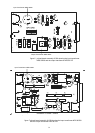
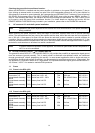
11. Fuses
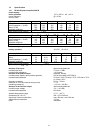
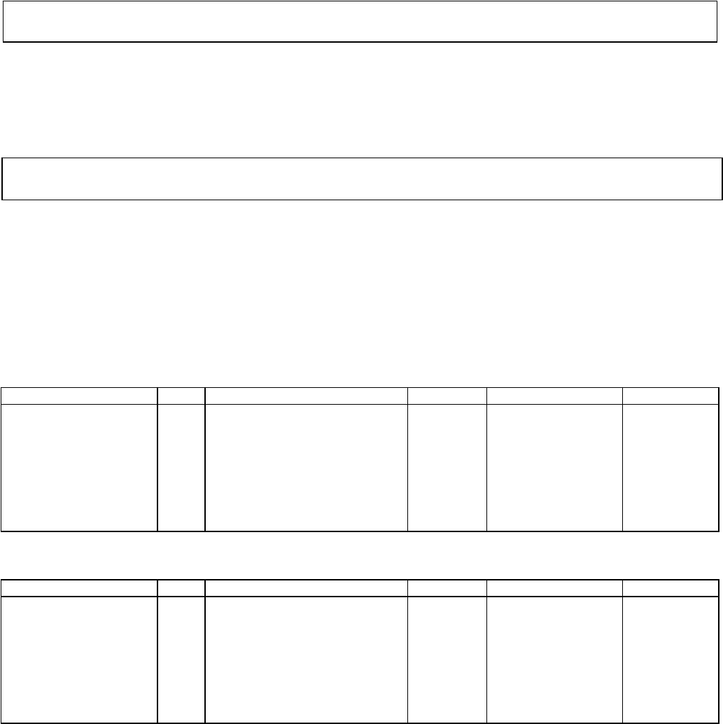
11.1 Fuses in the DPA 4120
location
Pos. purpose value dimensions standard
fuse socket (11) F601 mains fuse 230V~ AC T2A 5x20 mm IEC 127-2-3
fuse socket (11) F601 mains fuse 115V~ AC T4A 5x20 mm IEC 127-2-3
printed board assembly
86243
F602 mains fuse 100V - 250V T1A Ø 8.5xRM 5.08mm IEC 127-3/4
printed board assembly
85270
F502 battery fuse 24V DC 15A flat fuse DIN 72581-3
printed board assembly
85270
F503 battery fuse 24V DC 15A flat fuse DIN 72581-3
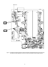
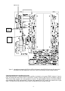
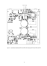
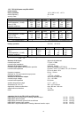
11.2 Fuses in the DPA 4140
location Pos. purpose value dimensions standard
fuse socket (11) F601 mains fuse 230V~ AC T4A 5x20 mm IEC 127-2-3
fuse socket (11) F601 mains fuse 115V~ AC T8A 5x20 mm IEC 127-2-3
printed board assembly
86243
F602 mains fuse 100V - 250V T1A Ø 8.5xRM 5.08mm IEC 127-3/4
printed board assembly
85268
F502 battery fuse 24V DC 25A flat fuse DIN 72581-3
printed board assembly
85268
F503 battery fuse 24V DC 25A flat fuse DIN 72581-3
38