


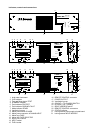

The remote module allows to remotely control and monitor the operation of the power amplifiers DPA 4120 and
DPA 4140 from the PROMATRIX manager DPM 4000 (for further details please refer to the PROMATRIX
handbook).
Caution: Before installing the input module NRS 90222, you have to unplug the mains connector as well as
a presumably connected battery cord.
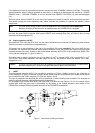
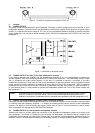
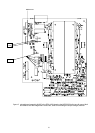
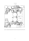
Before installing the input module, it is necessary to remove the two locking screws B on the rear panel of the
appliance. For installation the printed board assembly first has to be inserted into the guiding rails. After carefully
pushing the module in it has to be locked by using the two screws mentioned before.
Note After installing the remote module NRS 90222 it is necessary to set its address according to the
description in the PROMATRIX handbook using the two "HEX-code switches" ADDRESS (21) and
note the setting within the field ADDRESS on the rear panel of the appliance using a waterproof
marker pen.
8.3 NRS 90208 input transformer for the floating, balanced input
For the case that floating inputs are required, the inputs of the INPUT MODULE NRS 90225 and the REMOTE
MODULE NRS 90222 are prepared for retrofitting input transformers. If so, it is necessary to additionally install the
extension kit NRS 90208 per each input.
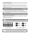
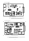
The installation has to be performed as follows (see figure 6 and/or figure 7):
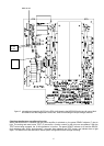
- to remove the input module you have to loosen the two locking screws (B) on the rear panel of the appliance.
Now, the module can be easily torn out.
- before installing the input transformer you have to remove the resistors R1 and R2.
- mount the input transformer onto the printed board assembly, so that the marking located on the connector side
of the transformer matches with the one on the printed board assembly. To prevent short-circuits place the
supplied insulation disc between the transformer and the printed board assembly.
- re-insert the input module and tighten the locking screws (B).
8.4 NRS 90227 output transformer for the floating, balanced monitor output
In case that floating monitor outputs are required, the outputs of the INPUT MODULE NRS 90225 and REMOTE
MODULE NRS 90222 are prepared for retrofitting output transformers. If so, it is necessary to additionally install
the extension kit NRS 90227 per each output.
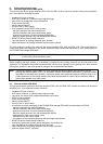
The installation has to be performed as follows (see figure 6 and/or figure 7):
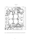
- to remove the input module you have to loosen the two locking screws (B) on the rear panel of the appliance.
Now, the module can be easily torn out.
- before installing the output transformer you have to remove the resistors R22, R23, R32 and R33 (NRS 90225)
respectively the resistors R23, R24, R71 and R72 (NRS 90222).
- now, you can mount the output transformer onto the printed board assembly. Because of the transformer's
symmetrical design, polarity is not a critical factor.
- re-insert the input module and tighten the locking screws (B).
33