


5.5 MONITOR output
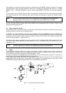
The MONITOR output (16) on the NRS 90225 allows the connection of an additional power amplifier for monitoring
purposes. The low impedance output is electronically balanced, which offers the possibility to achieve cable
lengths of up to 200 m. Connection is performed via the REMOTE CONTROL pin-connector strip (see also figure
4). For the remote control module NRS 90222, the MONITOR output is located on the REMOTE CONTROL
connector (22). The PROMATRIX manager DPM 4000 switches the signal to the according the monitor channel. In
case a floating output is required, the monitor output is prepared for retrofitting an output transformer; provided
through the optional extension NRS 90227 (please also refer to paragraph 8.4).
Note: Functioning changes in the models DPA 4120 (starting with serial numbers: 100 11) and DPA 4140
(starting with serial numbers: 100 11) in association with the input module NRS 90225: To achieve reliable
attenuation of switching noise (knacks), the monitor output stays muted as long as the READY-relay is not
pulled. Because of circuit design reasons this causes that the monitor output is also muted even when a
ground-fault appears at the main output.
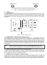
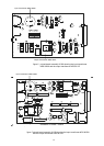
5.6 REMOTE CONTROL connector (only NRS 90225)
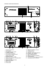
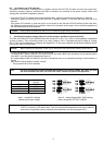
The 15-pole sub-D REMOTE CONTROL pin-connector strip (16) provides several different control in-/outputs:
- Ground of the stand-by power supply - negative pole grounded
- POWER REMOTE - via contact to ground potential
- BATTERY REMOTE - via contact to ground potential
- MONITOR output - electronically balanced
- READY-message - with floating contact
- Obligatory reception relay D-RELAY - via contact to ground potential
- Single call E-RELAY - via contact to ground potential
2 A STANDBY GROUND
3 POWER REMOTE
4 BATTERY REMOTE
5 D - RELAY
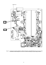
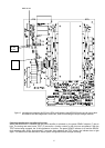
REMOTE CONTROL
6 E - RELAY
7
8 READY
15
9 + MONITOR
10 - MONITOR
figure 4 connections on the REMOTE CONTROL pin-connector strip
6. Indicators
6.1 STANDBY indicator
When the appliance is correctly connected and mains and/or battery power is present, the green STANDBY
indicator (4) will light.
6.2 READY indicator
Both amplifiers, the DPA 4120 and the DPA 4140, employ power-on switching delays of approximately 3 sec. to
effectively eliminate power-on switching noise. After this time, the green READY indicator (7) lights and the READY
fault message relay picks up when no error is being detected. When the power amplifier's mains transformer
exceeds a certain value or, when – with installed NRS 90224 extension – the pilot tone falls below the threshold
(see also paragraph 8.5.1), the green READY indicator (7) is not lit and the READY fault message relay drops.
6.3 PROTECT indicator
When thermal overload of the mains transformer or the power amplification stage is encountered, the red
PROTECT indicator (5) will light and the READY fault message relay drops. After the amplifier regained normal
temperature, the red PROTECT indicator (5) is automatically dimmed and the appliance returns to normal
operation. High temperature can be caused by overload, extreme ambient temperatures or faulty functioning of the
system's ventilation.
6.4 GROUND FAULT indicator
If, with the NRS 90224 extension installed, a ground fault is being detected at the power output, the red GROUND
FAULT indicator (6) will light and the READY fault message relay will drop. During the occurrence of this error
normal operation is maintained. After eliminating the cause for the ground fault, pressing the TEST button (3)
resets the GROUND FAULT indicator (6) (see also paragraph 8.5.2).
30