


20
REPLACING CD-ROM DRIVES
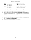
Address the TEAC drives for their location.
DTS-6D DTS-6 Termination programmed
TEAC 16X Drive A: Jumper 2, 4, 6 Jumper 2, 4, 6 on Pin 4, that should be
Drive B: Jumper 0, 2, 4, 6 Jumper 0, 2, 6 removed to activate.
Drive C: Jumper 0, 1, 6
TEAC 32X Drive A: Jumper 2 Jumper 2 Termination programmed
Drive B: Jumper 0, 2 Jumper 0, 2, 5 on Pin 5, that should be
Drive C: Jumper 0, 1, 5 added to activate.
8. Verify the “AQRM” chip is installed in the Acqutec ROM board. The AQRM chip must be
installed correctly.
9. Verify the Acqutec ROM and Adaptec SCSI boards are addressed as shown on page 6.
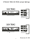
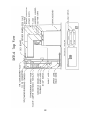
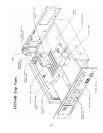
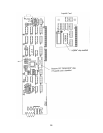
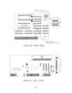
10. Install the Acqutec ROM and Adaptec SCSI boards. These boards must be used. See the “DTS-
6D” diagram for board orientation. It will be the same for the DTS-6 or DTS-6D. Use the saved
screw from the old SCSI board and a new #4 screw to mount both boards to player’s chassis.
NOTE: Bottom metal tab must be cut off for boards to fit correctly into unit.
11. Connect SCSI cable to Adaptec SCSI board. Check orientation of pin 1.
12. Apply power to player. Test the player by loading in the DTS DS1 Setup Disc. The player should
boot-up and automatically play the disc. Be sure the DIGITAL and CD-ROM L.E.D.s light. Check each
drive. All drives must be the same manufacturer.
13. Re-install the top cover and re-install the player into the sound rack.