


AVALON RF, INC. Page 4 of 28
DX404/DX504/DX604 User’s Guide & Operating Manual
2. Specifications
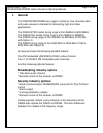
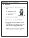
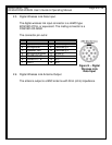
2.1 Power Input (Circle 9 on rear panel).
a) The power input connector is a XLR 4 pin on the rear panel of the
DX604.
Pin 1 – Ground
Pin 2 – RS232 Interface (Transmit)
Pin 3 – RS232 Interface (Receive)
Pin 4 - +9Vdc to +16Vdc
Figure C – Power Input
b) The DX604 operates off a 9Vdc to 16Vdc unregulated voltage
source with a ripple of less than 0.5Vp.p.
c) Input Current is under 1 Amp at an input voltage of 12Vdc.
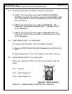
d) Power is switched via an ON/OFF mechanical switch.
e) The DX604 power input is protected against over voltage and
reverse polarity.
A bi-color LED on the rear panel indicates the condition. Yellow
indicates over voltage and Red indicates reverse polarity.
NOTE
f) The RS232 interface option on pins 2 and 3 is used to remotely
program and setup the DX604 as described in Appendix B.