


6
ENGLISH
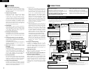
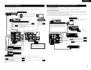
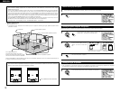
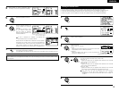
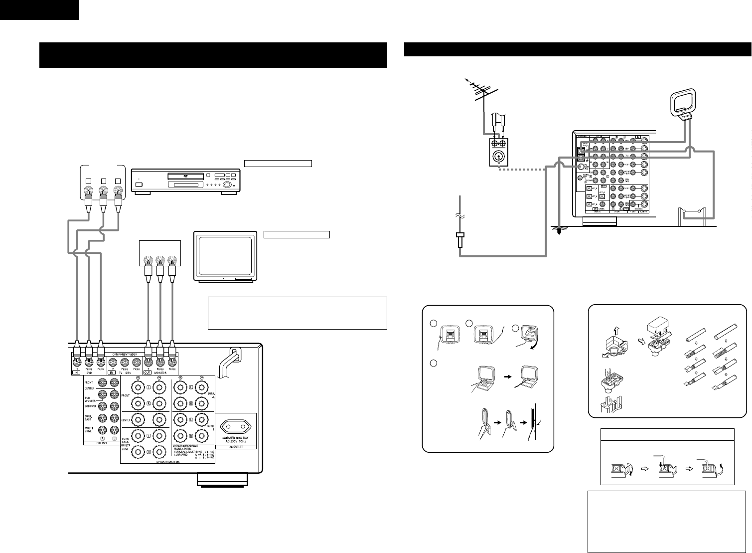
Connecting the antenna terminals
DIRECTION OF
BROADCASTING
STATION
75 Ω/ohms
COAXIAL
CABLE
FM ANTENNA
300 Ω/ohms
FEEDER
CABLE
FM INDOOR
ANTENNA
(Supplied)
300 Ω/ohms
AM LOOP
ANTENNA
(Supplied)
AM OUTDOOR
ANTENNA
GROUND
FM ANTENNA
ADAPTER
(Supplied)
• An F-type FM antenna cable plug can be connected directly.
• If the FM antenna cable’s plug is not of the F-type, connect using the included antenna adapter.
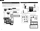
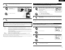
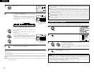
14mm
9mm
14mm
19mm
5mm
5mm
5C-2V3C-2V
1
4
2
3
AM loop antenna assembly FM antenna adopter assembly
Connect to the AM
antenna terminals.
Remove the vinyl tie
and take out the
connection line.
Bend in the reverse
direction.
a. With the
antenna on
top any
stable
surface.
b. With the
antenna
attached to
a wall.
Mount
Installation hole Mount on wall, etc.
75 Ω/ohms COAXIAL CABLE
Open the cover
ANTENNA ADAPTER
REMOVE
CLAMP
CLAMP
CLAMP
PULL
PULL
SHUT
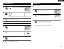
Connection of AM antennas
1. Push the
lever.
2. Insert the
conductor.
3. Return the
lever.
Notes:
• Do not connect two FM antennas
simultaneously.
• Even if an external AM antenna is used, do
not disconnect the AM loop antenna.
• Make sure AM loop antenna lead terminals
do not touch metal parts of the panel.
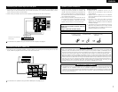
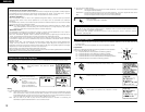
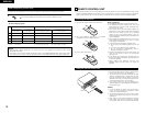
Y CRCB
VIDEO OUT
Y
CR CB
COMPONENT
VIDEO IN
COMPONENT
B
DVD player
Monitor TV
Connecting a DVD player
Connecting a monitor TV
DVD IN jacks
• Connect the DVD player’s color difference (component)
video output jacks (COMPONENT VIDEO OUTPUT) to the
COMPONENT DVD IN jack using 75 Ω/ohms coaxial video
pin-plug cords.
• In the same way, another video source with component
video outputs such as a TV/DBS tuner, etc., can be connected
to the TV/DBS color difference (component) video jacks.
MONITOR OUT jack
• Connect the TV’s color difference (component)
video input jacks (COMPONENT VIDEO INPUT)
to the COMPONENT MONITOR OUT jack using
75 Ω/ohms coaxial video pin-plug cords.
• The color difference input jacks may be indicated differently on some
TVs, monitors or video components (“CR, CB and Y”, “R-Y, B-Y and Y”,
“Pr, Pb and Y”, etc.). For details, carefully read the operating instructions
included with the TV or other component.
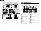
Connecting a Video Component Equipped with Color Difference (Component
- Y, P
R
/C
R
, P
B
/C
B
) Video Jacks (DVD Player)
• When making connections, also refer to the operating instructions of the other components.
• The signals input to the color difference (component) video jacks are not output from the VIDEO output jack
(yellow) or the S-Video output jack. In addition, the video signals input to the VIDEO input (yellow) and S-Video
input jacks are not output to the color difference (component) video jacks.
• The AVR-3802’s on-screen display signals are not output from the color difference (component) video output
jacks (MONITOR OUT).
• Some video sources with component video outputs are labeled Y, C
B, CR, or Y, P
b, Pr, or Y, R-Y, B-Y. These
terms all refer to component video color difference output.