


Operation Manual
CH and CL Series Power Amplifiers
page 24
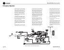
switch is set to 4/8 Ohm, only the negative and
4/8 ohm connections on the barrier block have
audio present. This provides power to low
impedance speakers. When the Channel Opera-
tion switch is set to 70V, only the negative and
70V connections on the barrier block have
audio present. This provides power to distrib-
uted speakers in a high-impedance “constant-
voltage” application.
The output relay, in conjunction with input sig-
nal mute circuit, assures a quiet turn-on and
turn-off. In the event of an amplifier output fail-
ure, a triac will activate to turn off the offending
channel to protect the speakers.
The turn-on delay circuit functions to keep the
output relay open until all the voltages are up
and stable, both in the amplifier, and in all the
components in the system ahead of the ampli-
fier.
Heatsink temperature is monitored by a thermal
probe attached to the heatsink. As the tempera-
ture rises, the probe sends a proportional cur-
rent to the proportional speed fan circuit which
starts the fan. Should the power transformer
reach its maximum safe temperature, an inter-
nal thermal switch opens and the fan circuit
turns on full speed to quickly cool down the
amplifier. It also disconnects the load via the
output relay, removing any output current and
further speeding a cool-down cycle. This point
is set both to protect speakers and to guard
against nuisance tripping.
Whenever the heatsinks or the transformer
reach a maximum temperature, or during the
normal turn on delay window, the front panel
Fault Indicators will blink.
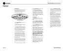
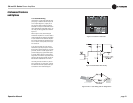
An RJ11 modular jack is mounted on the back
panel. Pins 2 and 5 are connected to an opto-
isolator which is always in a low-resistance
state whenever the unit is on and operational.
Should a fault be detected or should the ampli-
fier lose AC power, the opto-isolator will
change to a high resistance, allowing the user
to remotely detect the status of the amplifier.
The Signal Presence Indicators tap the signal
chain just before the level controls and prior to
the power amplifier chain. They are not ampli-
fier output indicators and should only be used
to indicate the presence of signal at the ampli-
fier front end.
The Clip Indicator is driven from the output of
the compressor circuitry and lights to indicate
the onset of audible distortion.
The Power Indicator LED is driven from the
low-voltage supply.
A positive and negative regulator form the ±15-
volt power supplies. Add to that the main trans-
former, a full-wave bridge rectifier, and high
energy electrolytic to form the main power sup-
ply. They are protected by the front-panel line
circuit breaker and controlled by the front-panel
power switch.
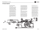
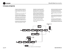
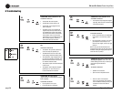
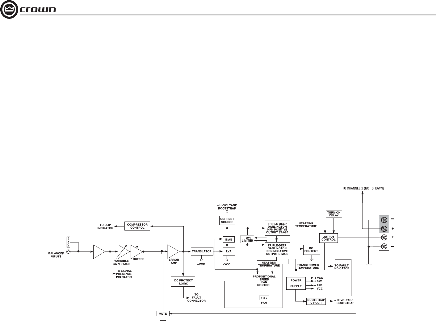
5 Principles of Operation
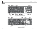
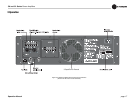
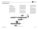
Figure 5.2 Models CL1 & CL2 Circuit Block Diagram
BALANCED
INPUT STAGE