


page 21
CH and CL Series Power Amplifiers
Operation Manual
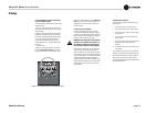
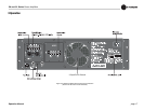
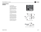
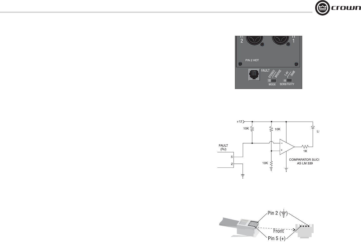
4.3.3 Fault Monitoring
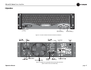
The Fault (RJ-11) jack, which looks like a tele-
phone plug, is located on the back of your CH
or CL amplifier (Figure 4.2). It gives you an
easy way to remotely monitor the amplifier’s
fault status. To set up a circuit that will cause an
LED to light whenever a fault status occurs, you
can simply use the suggested circuit shown in
Figure 4.3.
When using this circuit, the LED will glow
whenever the amplifier is in one of four states: a
channel’s heatsink has reached its temperature
limit, the transformer has reached its tempera-
ture limit, the amplifier has just been turned on
and is in its turn-on-delay mode, or the ampli-
fier is turned off.
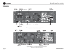
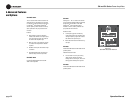
If you choose to design your own circuit to
interface this signal to your system, note that
this RJ jack is polarity sensitive. Pin 2 must be
grounded, and Pin 5 must be supplied with a
positive voltage pull up (positive with respect
to ground). Refer to Figure 4.4 for RJ jack pin
assignments. The maximum signal that can be
exposed to the fault jack is 35VDC and 10 mA.
Best results are obtained with 10 mA LEDs.
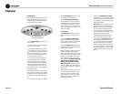
The mating connector for the RJ-11 jack con-
tains 4 contact pins in a 6-slot case, as shown.
For additional information please contact your
local dealer or Crown Technical Support.
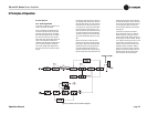
Figure 4.3 Fault Status LED Circuitry
Figure 4.4 RJ-11 Jack Wiring and Pin Assignments
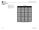
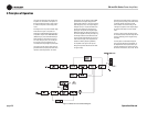
4 Advanced Features
and Options
Figure 4.2 Location of Fault Jack