


Micro-Tech 1200 Amplifier Service Manual
15
Electrical Checkout Procedures
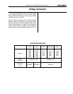
Spec at 4 Ohm Stereo: >= 470W at 0.1% THD.
Spec at 2 Ohm Stereo: >= 600W at 0.1% THD.
International 8 Ohm Stereo: >=305W at 0.1% THD.
International 4 Ohm Stereo: >=430W at 0.1% THD.
International 2 Ohm Stereo: >=535W at 0.1% THD.
Initial Conditions: Controls per standard.
Procedure: Load each channel to 8 ohms. Inject a 1 kHz
sine wave and measure at least 50.60 VAC at the output
of each channel. Load each channel to 4 ohms. Inject a
1 kHz sine wave and measure at least 43.36 VAC. Load
each channel to 2 ohms. Inject a 1 kHz sine wave and
measure at least 34.64 VAC. All power measurements
must be at less than 0.1% THD.
TEST 13: REACTIVE LOADS
Spec: No oscillations. Safe with all types of loads.
Initial Conditions: Controls per standard.
Procedure Capacitive: Load each channel to 8 ohms in
parallel with 2 µF. Inject a 20 kHz sine wave with 33 VAC
output for 10 seconds.
Procedure Inductive: Load each channel to 8 ohms in
parallel with 159 µHenries. Inject a 1 kHz sine wave with
20 VAC output for 10 seconds.
Procedure Torture: Load each channel with the primary
(red and black leads) of a DC-300A transformer (D 5781-
6). Inject a 15 Hz sine wave at sufficient output level to
cause 3 to 5 flyback pulses, for 10 seconds.
Procedure Short: Inject a 60 Hz sine wave at 20 VAC
output. After establishing signal, short the output for 10
seconds.
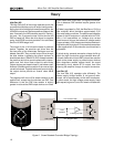
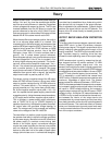
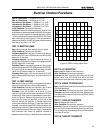
TEST 14: ODEP LIMITING
Spec: No oscillation on ODEP Limiting wave form; either
channel controls limiting in Parallel Mono Mode.
Initial Conditions: Controls per standard; rag or other
obstruction blocking fan so that it does not turn.
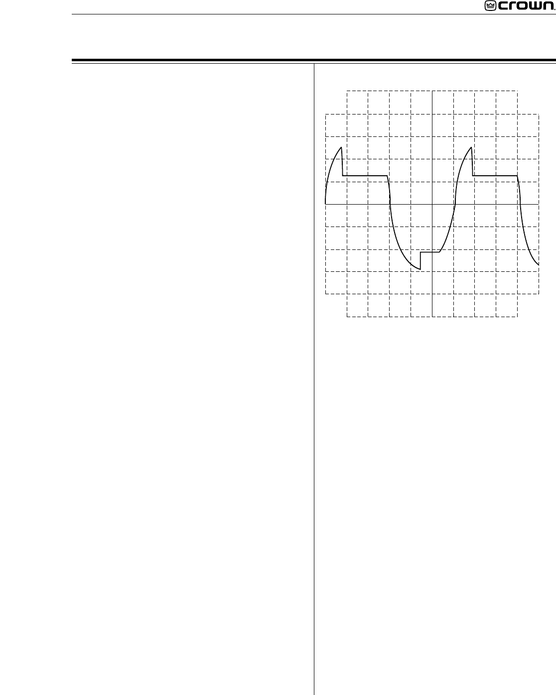
Procedure: Load the amplifier to 2 ohms on each
channel. Inject a 60 Hz sine wave and adjust for 20 Vrms
at the output. After a few minutes observe a wave form
similar to Figure 5. Remove the input signal from both
channels and allow the amplifier to cool for a few
minutes. Switch the amplifier to Parallel Mono and
remove the load from Channel 1. Inject the signal into
Channel 1 and observe that ODEP limiting occurs at the
output of both channels. Remove the load from Channel
2, and install the load on Channel 1. Again, observe that
both channels limit. Return all amplifier controls to
standard initial conditions. Remove the fan obstruction.
TEST 15: LF PROTECTION
Spec: Amplifier mutes for low frequency.
Initial Conditions: Controls per standard.
Procedure: No load. Inject a 0.5 Hz 6 volt peak-to-peak
square wave, or a 2 Hz 6VAC sine wave into each
channel and verify that each channel cycles into mute.
TEST 16: SIGNAL TO NOISE RATIO
Spec: 100 dB below rated 8 ohm power 20 Hz to 20 kHz.
105 dB A-Weighted.
Initial Conditions: Controls per standard. Short inputs.
Procedure: Load each channel to 8 ohms. Measure less
than 506 µV at the output of each channel (20 Hz-20 kHz
bandpass filter).
TEST 17: TURN ON TRANSIENTS
Spec: No dangerous transients.
Initial Conditions: Controls per standard.
Procedure: From an off condition, turn on the amplifier
and monitor the output noise at the time of turn on. Note:
Turn on noise may increase significantly if the amplifier
is cycled off and on.
TEST 18: TURN OFF TRANSIENTS
Figure 5. ODEP Limiting Wave Form