Micro-Tech 1200 Amplifier Service Manual
10
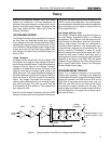
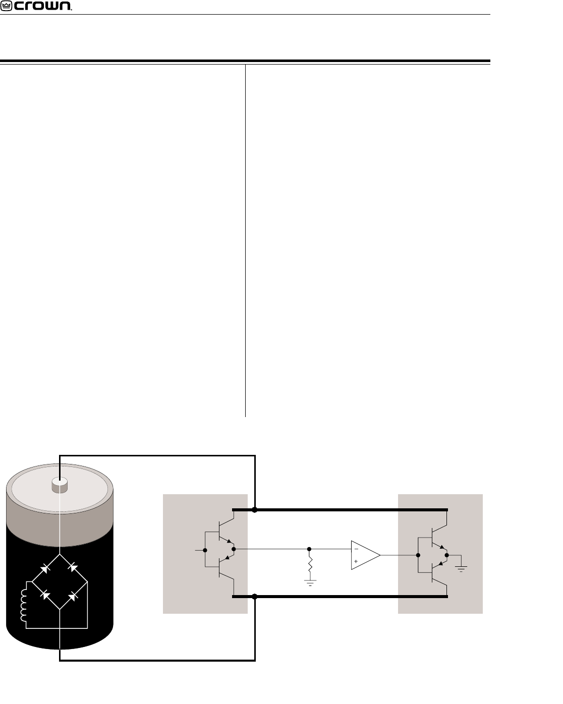
High Side (HS)
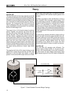
The High Side (HS) of the bridge operates much like
a conventional bipolar push-pull output configuration.
As the input drive voltage becomes more positive, the
HS NPN conducts and delivers positive voltage to the
load. Eventually the NPN devices reach full conduc-
tion and +Vcc is across the load. At this time the HS
PNP is biased off. When the drive signal is negative
going, the HS PNP conducts to deliver -Vcc to the load
and the HS NPN stage is off.
The output of the +LVA drives the base of predriver
device. Together, the predriver and driver form the
first two parts of the three-deep Darlington and are
biased class AB. They provide output drive through
the bias resistor, bypassing the output devices, at
levels below about 100mW. An RLC network between
the predriver and driver provide phase shift compen-
sation and limit driver base current to safe levels.
Output devices are biased class B, just below cutoff.
At about 100mW output they switch on to conduct high
current to the load. Together with predriver and driver,
the output device provide an overall class AB+B
output.
The negative half of the HS is almost identical to the
positive half, except that the devices are PNP. One
difference is that the PNP bias resistor is slightly
greater in value so that PNP output devices run closer
Theory
+
-
+Vcc (Positive Rail)
-Vcc (Negative Rail)
Load
(speaker)
Input
signal
HIGH SIDE LOW SIDE
Inverting Op-amp
Figure 2. Crown Patented Grounded Bridge Topology
to the cutoff level under static (no signal) conditions.
This is because PNP devices require greater drive
current.
HS bias is regulated by Q18, the Bias Servo. Q18 is a
Vbe multiplier which maintains approximately 3.3V
Vce under static conditions. The positive and negative
halves of the HS output are in parallel with this 3.3V.
With a full base-emitter on voltage drop across
predrivers and drivers, the balance of voltage results
in approximately .35V drop across the bias resistors in
the positive half, and about .5V across the bias resistor
in the negative half. Q18 conduction (and thus bias) is
adjustable.
A diode string prevents excessive charge build up
within the high conduction output devices when off.
Flyback diodes shunt back-EMF pulses from reactive
loads to the power supply to protect output devices
from dangerous reverse voltage levels. An output
terminating circuit blocks RF on output lines from
entering the amplifier through its output connectors.
Low Side (LS)
The Low Side (LS) operates quite differently. The
power supply bridge rectifier is not ground refer-
enced, nor is the secondary of the main transformer.
In other words, the high voltage power supply floats
with respect to ground, but ±Vcc remain constant with


