


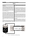
Micro-Tech 1200 Amplifier Service Manual
14
TEST 4: AC POWER DRAW
Spec: 100 Watts maximum quiescent.
Initial Conditions: Controls per standard.
Procedure: With no input signal and no load, measure
AC line wattage draw. If current draw is excessive,
check for high AC line voltage or high bias voltage.
TEST 5: COMMON MODE REJECTION
Spec at 100 Hz: –70 dB.
Spec at 20 kHz: –50 dB.
Initial Conditions: Controls per standard.
Procedure: No load. Inject a 0 dBu (.775VRMS) 100 Hz
sine wave into each channel, one channel at a time, with
inverting and non-inverting inputs shorted together. At
the output measure less than –44 dBu (4.9mVRMS).
Inject a 0 dBu 20 kHz sine wave into each channel, one
channel at a time, with inverting and non-inverting
inputs shorted together. At the output measure less
than –24 dBu (49mVRMS). For Main Modules with board
numbers lower than D 7993-5 adjust N100 and N200 to
calibrate CMR. For Main Modules with board number D
7993-5 or greater adjust R921 and R1021.
TEST 6: VOLTAGE GAIN
Spec 26dB Gain: Gain of 20.0 ±3%.
Spec 0.775V Sensitivity: ±6%.
Spec 1.4V Sensitivity: +12%/–6%.
Initial Conditions: Controls per standard.
Procedure: No load connected. Inject a 0.775 VAC 1 kHz
sine wave with the Sensitivity Switch in the 26 dB
position. Measure 15.5 VAC ±0.5 VAC at the amplifier
output. Inject a 0.775 VAC 1 kHz sine wave with the
Sensitivity Switch in the 0.775V position. Measure 50.6
VAC ±3 VAC at the amplifier output. Inject a 1.4 VAC 1
kHz sine wave with the Sensitivity Switch in the 1.4V
position. Measure 50.6 VAC +6/–3 VAC at the amplifier
output. Return the Sensitivity Switch to the 26 dB
position.
TEST 7: PHASE RESPONSE
Spec: ±10° from 10 Hz to 20 kHz at 1 Watt.
Initial Conditions: Controls per standard, 8 ohm load on
each channel.
Procedure: Inject a 1 kHz sine wave and adjust for 1 Watt
output (2.8 VAC). Check input and output signals
against each other, input and output signals must be
within 10° of each other.
TEST 8: LEVEL CONTROLS
Electrical Checkout Procedures
Spec: Level controlled by level controls.
Initial Conditions: Controls per standard.
Procedure: No Load. Inject a 1 kHz sine wave. With level
controls fully clockwise you should see full gain. As
controls are rotated counterclockwise, observe similar
gain reduction in each channel. When complete, return
level controls to fully clockwise position.
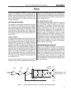
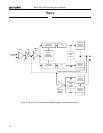
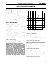
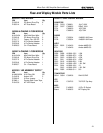
TEST 9: CURRENT LIMIT
Spec: Current Limit at 30 Amps, ±2 Amps
Initial Conditions: Controls per standard.
Procedure: Load each channel to 1 Ohm. Inject a 1 kHz
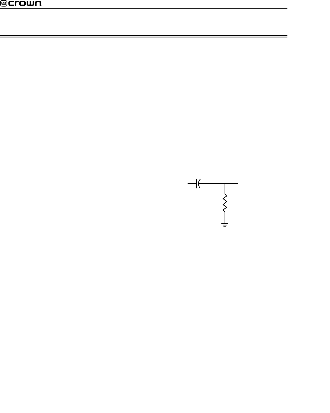
differentiated (or 10% duty cycle) square wave. See
figure 4. Increase output level until current limit occurs.
Current limit should occur at 30 ±2 Amps (30 Vpk).
Observe clean (no oscillations) current clipping.
In
Out
.047 uF
1K Ohm
Figure 4. Differentiator Circuit
TEST 10: SLEW RATE & 10 KHZ SQUARE WAVE
Spec: 13 - 15 V/µS.
Initial Conditions: Controls per standard.
Procedure: Load each channel to 8 ohms. Inject a 10 kHz
square wave to obtain 65 volts zero-to-peak at each
output. Observe the slope of the square wave. It should
typically measure 13 to 15 V/µS. Also, the square wave
must not include overshoot, ringing, or any type of
oscillation.
TEST 11: CROSSTALK
Spec: -60dB at 20 kHz.
Initial Conditions: Controls per standard. Terminate
input of channel not driven with 600 ohms.
Procedure: 8 ohm load on each channel. Inject a 20 kHz
sine wave into the Channel 1 input and increase output
level to 33 VAC. Measure less than 33 mVAC at the
output of Channel 2. Inject a 20 kHz sine wave into the
Channel 2 input and increase output level to 33 VAC.
Measure less than 33 mVAC at the output of Channel 1.
TEST 12: OUTPUT POWER
Spec at 8 Ohm Stereo: >= 320W at 0.1% THD.