


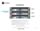
I-Tech HD Series Power Amplifi ers
Operation Manual
page 9
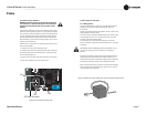
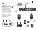
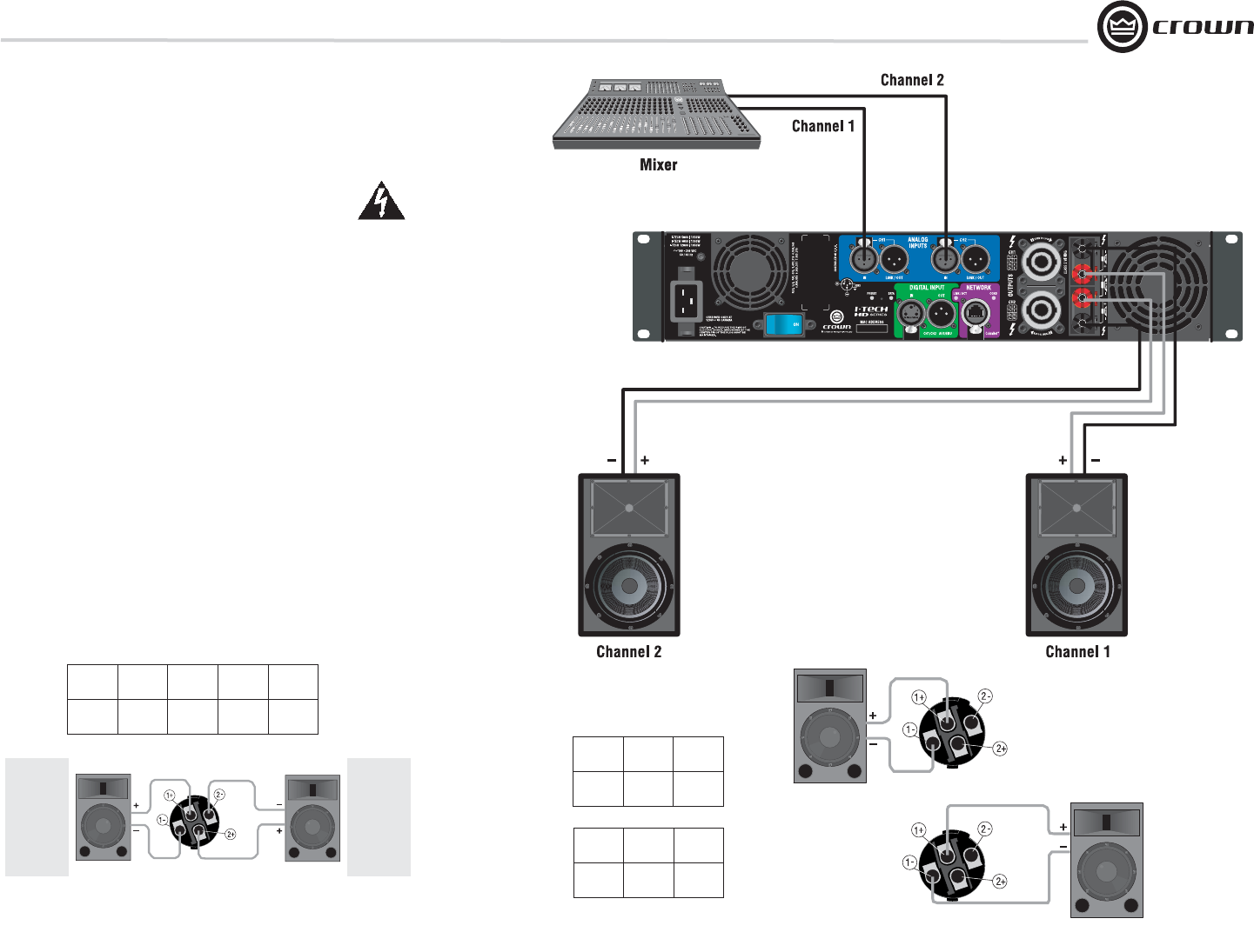
2.3.4 Stereo Mode Wiring
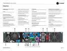
Typical input and output wiring is shown in Figure 2.9.
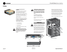
IMPORTANT: Turn off the amplifi er and unplug its power cord.
INPUTS: Choose one of these options:
• Connect analog input wiring for both channels.
• Connect an AES/EBU digital signal to the AES/EBU connector.
OUTPUTS: Maintain proper polarity (+/–) on output connectors. Use
Class 2 output wiring.
Figure 2.9 shows how to wire stereo speakers to the binding posts.
Con nect Channel 1 loudspeaker’s positive (+) lead to Channel 1 positive
(red) terminal of amp; repeat for negative (–). Repeat Channel 2 wiring as
for Channel 1.
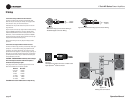
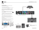
To wire stereo speakers to the Speakon
®
connectors, use one of these
methods:
Method 1 (Table 1 and Figure 2.10): Wire one Speakon
®
cable connector
to two speakers. Insert the Speakon
®
cable connector into the amplifi er’s
top Speakon
®
connector.
Method 2 (Table 2 and Figure 2.11): Plug the Channel 1 speaker into the
Channel 1 (top) Speakon
®
connector, and plug the Channel 2 speaker
into the Channel 2 (bottom) Speakon
®
connector.
2 Setup
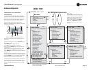
Figure 2.10 Wiring Two Stereo Speakers
to the Top Speakon
®
Connector
PIN 1+ 1– 2+ 2–
CH 1+ 1– 2+ 2–
Stereo Wiring Method 1: Use Top Speakon
®
Only
Table 1
PIN 1+ 1–
CH 2+ 2–
PIN 1+ 1–
CH 1+ 1–
Stereo Wiring Method 2: Use Both Speakon
®
s
Channel 1
Loudspeaker
Channel 2
Loudspeaker
Top Speakon
(Channel 1)
Bottom
Speakon
(Channel 2)
Channel 1
Loudspeaker
Enceinte du
Canal 1
Lautsprecher
Kanal 1
Altoparlante
del Canal 1
Channel 2
Loudspeaker
Enceinte du
Canal 2
Lautsprecher
Kanal 2
Altoparlante
del Canal 2
Figure 2.9
System Wiring,
Stereo Mode
Figure 2.11
Stereo Wiring
Using Both
Speakon
®
Connectors
Top
Bottom
Table 2