


Operation Manual
I-Tech HD Series Power Amplifi ers
page 10
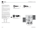
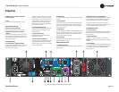
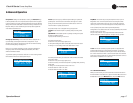
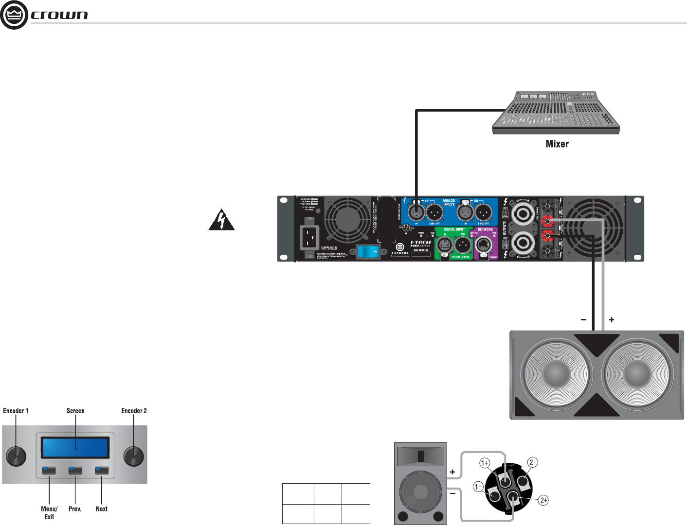
Figure 2.14
Wiring a Speaker in Bridge-Mono Mode to
the Top Speakon
®
Connector
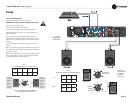
Table 3
Top Speakon
®
Wiring for Bridge-Mono
PIN 1+ 2+
SPKR
+–
2 Setup
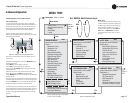
2.3.5 Bridge-Mono Mode
Overview: Turn on the amp, enable Bridge-Mono mode using the LCD Control
Screen, turn off the amp, wire it, and turn it back on.
1. Be sure that no cables are connected to the amplifi er. Turn on the front-panel power
switch. The LCD Control Screen will light up (Figure 2.12).
2. Under the LCD Control Screen, press the Menu/Exit button. Press the Next
button until you see OUTPUT MODE on the screen. If N/A is displayed, OUTPUT
MODE is locked via software. If LOCKOUT is displayed, all the LCD screens are
locked via software.
3. Press an Encoder knob to select BRIDGE MONO. Press the knob again to confi rm
your choice. Press Menu/Exit. Turn down both level controls (Encoders) until you
reach maximum attenuation.
4. IMPORTANT: Turn off the amplifi er and unplug its power cord.
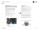
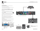
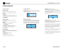
INPUTS: There are three ways to connect an input signal to the amplifi er (Figure
2.13):
• Connect an analog signal source to the Channel-1 amplifi er input.
• Connect an AES/EBU digital signal source to the Digital Input IN connector.
NOTE: Crown provides a reference of wiring pin assignments for commonly used
connector types in the Crown Amplifi er Application Guide available at
www.crownaudio.com.
OUTPUTS: Use Class 2 output wiring. There are two ways to wire the amplifi er output
connectors for Bridge-Mono mode:
1) Wire the speaker across the red binding post of each channel (Figure 2.14). Do not
use the black binding posts when operating in Bridge-Mono mode.
2) Wire the speaker only to the top Speakon
®
connector as shown in Table 3 and
Fig ure 2.14.
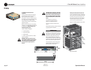
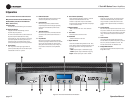
Figure 2.12
The LCD Control Screen
NOTE: In Bridge-Mono
mode, the Channel 1
Level control sets the
level; the Channel 2 Level
control is defeated. All
Channel-2 objects and
controls are hidden and
disabled.
Menu/Exit Prev Next
Figure 2.13 Bridge-Mono Wiring to Binding Posts