


4–5Principles of Operation
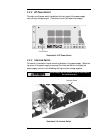
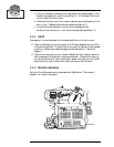
4.2.1 AC Input Board
The AC Input Board is located on the left side of the PS1000. AC power from the
circuit breaker connects to the AC Input Board where it connects to a ±12 volt DC
power supply and three relays. The ±12 volts is used to close the three relays when
the DC Power Switch on the front panel is switched on. In addition, the ±12 volts
are supplied to the PA1000 for use in the Control and Metering Board. The 240-
volt AC input to the power supply is connected through a Hubble Twist Lock
connector on the back panel to a 20–amp circuit breaker mounted inside the back
panel.
When the power supply is turned on and enabled, the AC power comes through
torroidal inductors which prevent harmonics and spurious products from feeding
back into the AC power lines. The current flows from the inductors to a bridge
rectifier that converts the current to DC Power, and from there to the PFC Switch-
ing Board where the rectified DC is filtered. The filtered DC power is then fed from
the PFC Switching Board through an 80–turn boost inductor and back to the PFC
Switching Board.
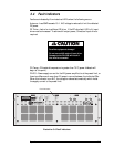
4.2.2 PFC (Power Factor Correcting) Switching Board
The PFC Switching Board is located directly behind the cooling fans (front panel) in
the PS1000. This board takes the voltage from the Torroidal Boost Inductor and
sends it to the Boost Switching Transistor. The switching transistor chops the DC
input power at a 25 kHz rate. The chopped voltage is then rectified, filtered, and
sent as DC voltage to a set of four transistors which form a second switching stage.
The second switching stage chops the DC voltage at a 22.5 kHz rate. This chopped
DC power is fed through a blocking capacitor to a transformer on the DC Output
Board. The second switching stage controls the amount of power sent to the DC
Output Board. This ensures that the transformer output voltage and current are
correct for providing the selected RF output power to the amplifier.