


2–7
Installation
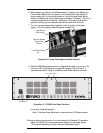
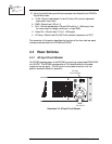
For remote I/O (Input/Output) connection, connect your remote I/O cable from
your remote control location to the 25–pin (female) D-sub connector on the back
panel of the PA1000. The I/O Connector on the power amplifier is described in the
following diagram:
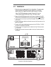
The Remote I/O Connector Pinout Table on the next page summarizes the Remote
I/O pin connections.
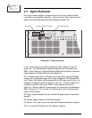
1
25
13
14
View from Rear of Cabinet
Illustration 2–7 Remote I/O connector (back panel view)
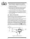
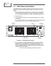
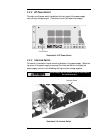
Illustration 2–6 On-board Remote Power & Related Controls
Local/Remote
Slide Switch
On-board Remote
Power Adjust
Buttons
Local Power Adjust
Pot
Another remote control function, available at pin 5 of the Remote I/O Connector,
turns RF down/off. Connecting this pin to ground through a resistor allows the
RF power output level of the amplifier to be reduced below the internal limit set by
the Local Power Adjust pot or the remote Raise/Lower settings. However, some
drive power, less than one watt, may still be present at the antenna. Depending on
the resistor used, this pin can serve as a control for optional low power operation.
The remaining remote functions are for monitoring the various
parameters of the PA1000. They are either buffered metering outputs, direct
reading, or latched high/low indications. Further details of these functions are
described in the pin-out table on page 2–8.
Note: If Remote I/O controls are not used, tie pin 7 to pin 6 (GND.).
the level up to that limit and down to zero. When a specific output power level is
set, the Metering and Control Board controls and maintains the setting to keep the
power constant. The location of the Local Power Adjust (R62), the on-board Raise
and Lower switches (SW3 & SW4), and the Local/Remote slide switch (SW5) are
shown below.